
Page 15 - QR IMER STEP120
P. 15
tS'~ IMER INTERNATIONAL S.p.A.
SPIN 15
OVERLOAD AND ELECTRICAL PROTECTIONS the machine and pipes. Also disassemble the pump, remove the
screw from the stator and clean. On completion reassemble all
& - The electric motors are protected against overload components.
Refit the pump taking care to insert the mixer in the envisaged
by thermal magnetic cut-outs, the activation of which is seats.
indicated by total shutdown of the machine. In this case,
after the motors have cooled, the specific personnel
should reset the main switch to resume operation.
Activation of these safety devices is indicated by illumi
nation of a red light (ref. 7), in which case, authorised
persona personnel must remedy the cause and reset the
safety device via the main switch, turning it from 0 to 1.
- The main switch on the electrical panel (ref. 6) is only
enabled when: power is connected to the protection grid
or the vibroscreen is fitted on the machine.
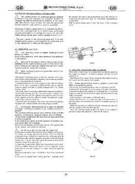
12. OPERATION (see fig.1)
& - The vibrating screen or hopper safety grid must
always be fitted.
Never place materials other than premixed wet materials
in the hopper.
& -Removal of the hopper grid or vibro-screen causes
FIG 9
shutdown of the machine moving parts. If this occurs, the
grid or vibro-screen must be refitted and the main switch
must be reset to restart the machine.
i l l - 13. MACHINE SHUTDOWN AND CLEANING
Wear envisaged personal protection devices beAt the end of w
ork, stop the machine after completely emptying
fore starting work
the hopper by means of the relative selector and set the main
Interruptions exceeding 30min should be avoided, and in any switch to O.
event these pauses should be reduced to the minimum possible - Open the jet valve, detach the jet and clean thoroughly, cleaning
when using rapid-drying materials the nozzle with the special tool supplied.
Prolonged shutdown can cause clogging in the material delivery
i l l -Before disconnecting the jet or pipelines, ensure that
there is no residual pressure.
lines: in this case no material is delivered from the jet and the
pressure gauge indicates a higher pressure than the normal -Disconnect the material pipelines from the delivery manifold.
working value. -Remove the hopper grid or vibro-screen and clean thoroughly
In this case, tum the selector anticlockwise (opposite position to -Remove the plug at the bottom of the hopper (fig. 11) and use
normal work setting) (ref. 8). the pump motor rotates in the water to wash the machine thoroughly, starting from the bag
opposite direction and the pipelines are depressurised. As soon splitter if installed.
as the pipeline becomes soft and flexible (the pressure gauge - Refit the plug in the hopper and fill with water.
reads 0 bar), stop the machine. -Restart the machine for a few seconds until clean water is
Locate the point of clogging in the hose and remove by tapping delivered from the manifold: this confirms complete cleaning of
the hose with a rubber mallet and totally empty by hand. the pump.
& -If necessary, disconnect the jet or open the pipeline
- While the pipelines are still full, insert two cleaning sponges and
refit the pipeline in the manifold (fig. 10)
couplings, checking previously if any residual pressure is
- Start the machine again so that the water in the hopper is
pumped through the pipelines to remove all residue.
present.
The material pressure gauge must indicate 0 bar and the
pipelines, excluding the clogged sections, must be flexible.
The personnel assigned for this task must be specially trained
in these procedures.
In the event of any doubt as to the presence of residual pres
sure, never open the couplings.
Reconnect the pipelines and spray jet, set the main switch to the
correct position and restart the machine.
& -Do not move the machine with the hopper full.
A reduction in material flow to the jet may indicate a worn pump.
To replace the pump, proceed as follows: with the machine
empty and clean, remove the vibrating screen or hopper grid, tilt
the machine with manifold upwards, unscrew the tie-rod locking
screws (ref. 1, fig. 9), and at the same time remove the delivery
manifold, screw and stator (fig. 9).
To insert the screw in the stator, use the lubricant spray avail
able from IMER. Never use mineral oil or grease for screw
assembly as this may damage the stator. Avoid all types of
benzene.
Refit the pump taking care to insert the mixer in the envisaged
seats.
In the case of a power failure during operation, promptly wash FIG 10
29