
Page 7 - April 2020_Neat
P. 7
7
April 2020 Return to Start
www.tswfl.org `Triumphs Live Page 7
On’
Tech Corner-continued
your feeler gauge. If it has changed from the light drag you felt originally, loosen the nut and start over again.
Continue until the nut is tight and you’re certain that the clearance is as specified, then move on to the next one.
Rotate the engine with the fan blade and watch valve #2. When it is fully open, and seen to just begin to come
up (close), you’ll know that it’s time to adjust valve #7 (2+7=9). Continue working your way toward the rear of
the engine, watching each successive valve open fully, and adjusting the valve whose number added to the open
one adds up to 9. When you reach the rear of the engine, valve #8 is open and you’ve adjusted #1, all of your
valves will have been adjusted, and the job is done.
As I mentioned before, this “Rule of 9” works on the Triumph TR2-4A engines, but it doesn’t necessarily work
for every engine, or the 6-cylinder TR engines. For that reason, I prefer to adjust valves on a cylinder by cylinder
basis, so that I know what’s going on with the camshaft of any engine I might be working on.
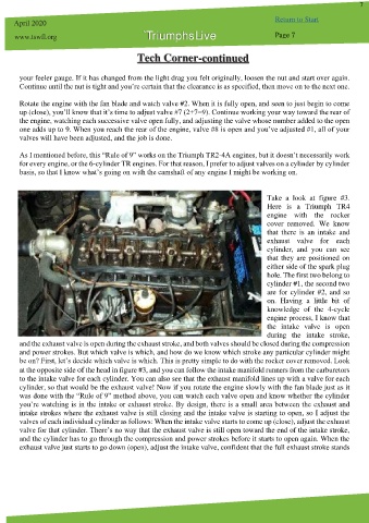
Take a look at figure #3.
Here is a Triumph TR4
engine with the rocker
cover removed. We know
that there is an intake and
exhaust valve for each
cylinder, and you can see
that they are positioned on
either side of the spark plug
hole. The first two belong to
cylinder #1, the second two
are for cylinder #2, and so
on. Having a little bit of
knowledge of the 4-cycle
engine process, I know that
the intake valve is open
during the intake stroke,
and the exhaust valve is open during the exhaust stroke, and both valves should be closed during the compression
and power strokes. But which valve is which, and how do we know which stroke any particular cylinder might
be on? First, let’s decide which valve is which. This is pretty simple to do with the rocker cover removed. Look
at the opposite side of the head in figure #3, and you can follow the intake manifold runners from the carburetors
to the intake valve for each cylinder. You can also see that the exhaust manifold lines up with a valve for each
cylinder, so that would be the exhaust valve! Now if you rotate the engine slowly with the fan blade just as it
was done with the “Rule of 9” method above, you can watch each valve open and know whether the cylinder
you’re watching is in the intake or exhaust stroke. By design, there is a small area between the exhaust and
intake strokes where the exhaust valve is still closing and the intake valve is starting to open, so I adjust the
valves of each individual cylinder as follows: When the intake valve starts to come up (close), adjust the exhaust
valve for that cylinder. There’s no way that the exhaust valve is still open toward the end of the intake stroke,
and the cylinder has to go through the compression and power strokes before it starts to open again. When the
exhaust valve just starts to go down (open), adjust the intake valve, confident that the full exhaust stroke stands