
Page 1362 - Workshop Manual - Aumark (BJ1051)
P. 1362
61-90
Circuit-Information of wire insert parts
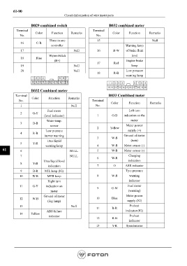
B029 combined switch B032 combined meter
Terminal Terminal
Color Function Remarks Color Function Remarks
No. No.
Three in one 15 Null
16 C-B
controller Warning lamp
17 Null 16 B-W of brake fluid
Wiper switch level
18 Blue
(B+) Engine brake
17 Red
19 Null lamp
20 Null Low pressure
18 R-B
warning lamp
B032 Combined meter
Terminal B033 Combined meter
Color Function Remarks
No. Terminal
Color Function Remarks
1 Null No.
Fuel meter Left turn
2 G-Y
(level indicator) 1 G-B indication on the
Water temp. meter
3 B-B
sensor Meter power
2 Yellow
Low pressure supply (+)
4 R-B
buzzer warning Ground of meter
3 W-B
Urea liquid (turn)
5 Y-R
warning lamp 4 W-B Meter sensor (-)
61 6 NULL 5 W-B Meter sensor (-)
7 NULL Charging
6 W-R
Urea liquid level indication
8 Y-B
indication 7 O ASR indicator
9 B-R MIL lamp (IG) Tyre pressure
10 W-R MTII lamp 8 W-B warning
Right turn indicator
11 G-Y indication on Fuel meter
9 G-W
meter (warning)
Ground of meter Meter power
12 W-B 10 Blue
(fog lamp) supply (IG)
13 Null Preheat
11 B-R
ABS failure indicator (IG)
14 Yellow
indicator Preheat
12 R-B
indicator
13 Y-R Speedometer
Page 1362