
Page 37 - Gi flipbook_May 2019
P. 37
igem news – yppc
FIGURE 3 MAP OF GAS NETWORK SUPPLYING BEAL INDICATING HOLYGARTH LANE FIGURE 4 MAP OF GAS NETWORK WITH FLOOD MAPPING AND LOW POINTS (ELEVATION)
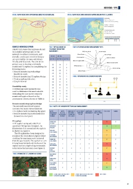
Remotely monitored syphon TABLE 1 WET GAS AND DRY GAS FIGURE 6 PE SYPHON ASSEMBLY WITH COMPONENT PARTS
IGEM/TD/3 states that syphons should THRESHOLDS FOR DEW POINT
be installed at low points on the MEASUREMENTS
network to collect condensate, and
metallic condensate receiver designs dry gas wet gas
are specified in the now withdrawn dew point Oc dew point Oc dew point Oc
BS 785 and BS 47726. The aim of the
project was to develop a remotely -50 -24 2
monitored PE syphon by completing the -48 -22 4
following tasks:
Remote monitoring technology -46 -20 5
feasibility study -44 -18 6
Remote monitoring PE syphon design -42 -16 7 FIGURE 7 SYPHON IMPACT ON EXCAVATION DIMENSIONS
Testing and qualification -40 -14 8
G/23 field trial -38 -12 9
-36 -10 10
Feasibility study
A technology ranking matrix was -34 -8 11
used to determine the most suitable -32 -6 12
technology for use on the remotely -30 -4 13
monitored syphon based on the -28 -2 14
assessment criteria shown in Table 2: -26 0 15
Remote monitoring syphon design
The remotely monitored syphon TABLE 2 WATER LEVEL MEASUREMENT TECHNOLOGY RANKING SUMMARY
contains two main sub-assemblies:
PE syphon tank (containing dip-pipe) water water compatability cost of remote maintenance/ compatability total score ranking
with remote
fill level
Remote monitoring instrumentation measurement measurement transmitting monitoring maintainability with pe syphon
technology/
tank
system
(housed in a test post) technique capability data logger
PE syphon hydrostatic 1 5 3 3 3 15 8
A PE syphon using only GIS/PL27 pressure
approved fittings was designed. An differential 4 5 3 4 4 20 1
illustration of an assembled PE syphon pressure
is shown in Figure 6. displacer 4 4 3 3 2 16 7
The PE syphon has been designed to level sensors
minimise the excavation footprint whilst ultrasonic 4 5 2 4 3 17 3=
measurement
enabling the maximum water removal
from the gas network. The syphon is 1.2m conductive 4 4 3 3 3 17 3=
level switch
in length and is fitted with the base of the laser level 1 4 2 4 3 14 9=
syphon tank at a depth of approximately measurement
0.6m below the host main (see Figure 7). buoyancy 4 4 4 2 32 17 3=
float
detection
FIGURE 5 HYGROMETER TEST LOCATIONS AND RESULTS non-contact 1 4 2 3 3 13 11
radar
guided wave 4 4 2 2 2 14 9=
radar
float switch 4 4 3 4 2 17 3=
detection
capacitance 4 4 3 3 4 18 2
measurement
feasible (with few challenges feasible (with several challenges not feasible
to prototpe creatiion) to prototpe creatiion)
37
IGEMNews_YPPC.indd 2 16/04/2019 19:01