Page 65 - Tenob Online Catalogue Volume 5 Systems
P. 65
H GAUGES AND SENDERS
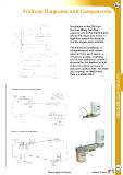
FloScan Diagrams and Components
Installation of the FloScan
involves fitting two flow
sensors, one in the fuel line and
one in the return line. A low or
high flow sensor is chosen to
suit the engine consumption.
The electrical installation is
straightforward with cables
returned from each sensor, a
12v power supply, a lighting
circuit plus additional switches
required for the totalizer and to
select from litres per hour to
litres per nautical mile. The 9500
also requires an NMEA feed
from a suitable GPS.
6A5
Total Supply Solutions... Marine Direct