
Page 20 - Test Catalouge
P. 20
Back to Main Menu
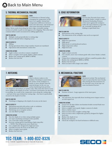
5. THERMAL MECHANICAL FAILURE 6. EDGE DEFORMATION
CAUSE CAUSE
A combination of thermal cycling Excessive heat. Excessive heat causes
(changing the temperature of the the carbide binder (cobalt) to soften.
insert very rapidly), thermal load Mechanical Overloading. Pressure
(temperature differences between of the insert against the workpiece
warm and cold zones), and mechanical makes the insert deform or sag at the
shock causes thermal mechanical tip, eventually breaking off or
failure. Stress cracks form along the insert edge, eventually causing leading to rapid flank wear.
sections of carbide to pull out and appear to be chipping. This is the most
common failure mode encountered in milling applications. WHAT TO LOOK FOR
Q Deformation at the cutting edge
WHAT TO LOOK FOR Q The dimensions of the workpiece may not be as expected
Q Multiple cracks perpendicular to cutting edge
Q Need to identify before chipping occurs WHEN TO EXPECT IT
Q High heat operations
WHEN TO EXPECT IT Q High speed
Q Milling Q Hard steels or work-hardened surfaces
Q Facing operations when a large number of parts are machined Q High temperature alloys
Q Operations with intermittent coolant flow Q High feed rates
CORRECTIVE ACTIONS CORRECTIVE ACTIONS
Q Apply coolant correctly or remove completely Q Apply coolant correctly
Q Select a tougher insert grade (higher cobalt content) Q Use a harder, more wear resistant grade with a lower binder (cobalt)
Q Reduce the cutting speed (RPM or SFPM) content
Q Reduce the feed rate Q Using a freer cutting insert geometry will have a small but positive effect
Q Reduce the cutting speed (RPM or SFPM)
Q Reduce the feed rate
Q Select an insert with a larger nose radius
7. NOTCHING 8. MECHANICAL FRACTURE
CAUSE CAUSE
Hard or abrasive surfaces on the Mechanical overload. The mechanical
workpiece. Notching is caused when load is so great that the insert breaks,
the surface of the workpiece is often during the first moments of a
harder or more abrasive than the cut. Excessive wear of any type can
material deeper in the cut, e.g. cause mechanical fracture.
surface hardening from previous
cuts, forged or cast surfaces, or surface scale. This causes the insert to wear
more rapidly at the depth of cut line. Local Stress Concentration can also lead WHAT TO LOOK FOR
to notching. As a result of the compressive stress along the cutting edge Q Fracture of insert. Large segments of the insert gone.
– and lack of the same behind the cutting edge – the insert is particularly
stressed at the depth of cut line. WHEN TO EXPECT IT
Q Any operation, but especially those involving severe impact such as
WHAT TO LOOK FOR an interrupted cut
Q Notching or chipping at the depth of cut area on the insert
CORRECTIVE ACTIONS
WHEN TO EXPECT IT Q Correct for all other failure mechanisms besides normal flank wear
Q Machining materials with surface scale or oxidation Q Verify set-up rigidity
Q Machining work hardened materials Q Select a tougher insert grade (higher content of cobalt)
Q Machining cast or irregular surfaces Q Select a thicker insert
Q (see also Built Up Edge) Q Select an insert with a tougher cutting edge
Q Select an insert with a chipbreaker geometry designed for higher
CORRECTIVE ACTIONS feed rates
Q Vary the depth of cut when using multiple passes Q Reduce the depth of cut
Q Use taper machining techniques when possible Q Reduce the feed rate
Q Use a tool with a larger lead angle Q Check the workpiece for hard inclusions or difficult entry
Q Increase cutting speed if machining a high temp alloy
– NOTE: This will generate more flank wear
Q Use a chipbreaker designed for high feed rates
Q Carefully increase the hone in the DOC area
Q Select a tougher insert grade
Q Reduce the feed rate
TEC-TEAM: 1-800-832-8326
GT13-5xx P-1303-2000 Copyright © 2013 Seco Tools, Inc. Printed in USA. All rights reserved.