
Page 19 - Test Catalouge
P. 19
Back To Main Menu
INSERT WEAR
FAILURE MODES
1. NORMAL FLANK WEAR 2. CRATERING
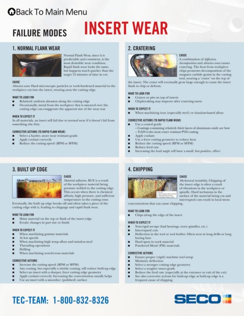
Normal Flank Wear, since it is CAUSE
predictable and consistent, is the A combination of diffusion,
most desirable wear condition. decomposition and abrasive wear causes
Rapid flank wear looks the same, cratering. The heat from workpiece
but happens much quicker than the chips promotes decomposition of the
target 15 minutes of time in cut. tungsten carbide grains in the cutting
tool, wearing a ‘crater’ on the top of
CAUSE the insert. The crater will eventually grow large enough to cause the insert
Abrasive wear. Hard microscopic particles or work-hardened material in the flank to chip or deform.
workpiece cut into the insert, wearing away the cutting edge.
WHAT TO LOOK FOR
WHAT TO LOOK FOR Q Craters or pits on top of inserts
Q Relatively uniform abrasion along the cutting edge Q Chipbreaking may improve after cratering starts
Q Occasionally, metal from the workpiece that is smeared over the
cutting edge can exaggerate the apparent size of the wear scar WHEN TO EXPECT IT
Q When machining iron (especially steel) or titanium-based alloys
WHEN TO EXPECT IT
In all materials, an insert will fail due to normal wear if it doesn’t fail from CORRECTIVE ACTIONS (TO RAPID FLANK WEAR)
something else first. Q Use a coated grade
– Coatings containing relatively thick layers of aluminum oxide are best
CORRECTIVE ACTIONS (TO RAPID FLANK WEAR) – TiAlN is the most crater resistant PVD coating
Q Select a harder, more wear resistant grade. Q Apply coolant
Q Apply coolant correctly Q Use a freer cutting geometry to reduce heat
Q Reduce the cutting speed (RPM or SFPM) Q Reduce the cutting speed (RPM or SFPM)
Q Reduce feed rate
Q Increasing the lead angle will have a small, but positive, effect
3. BUILT UP EDGE 4. CHIPPING
CAUSE CAUSE
Material adhesion. BUE is a result Mechanical instability. Chipping of
of the workpiece material being the insert edge is often a result
pressure welded to the cutting edge. of vibrations in the workpiece or
This occurs when there is chemical f = V/(5 x WL) spindle. Hard inclusions in the
affinity, high pressure, and sufficient f = vibration frequency (cycles per second) surface of the material being cut and
V = cutting speed (feet per minute)
WL = wave length of vibration (inches)
temperature in the cutting zone. interrupted cuts result in local stress
Eventually, the built up edge breaks off and often takes a piece of the concentrations that can cause chipping.
cutting edge with it, leading to chippage and rapid flank wear.
WHAT TO LOOK FOR
WHAT TO LOOK FOR Q Chips along the edge of the insert
Q Shiny material on the top or flank of the insert edge
Q Erratic changes in part size or finish WHEN TO EXPECT IT
Q Non-rigid set-ups (bad bearings, worn spindles, etc.)
WHEN TO EXPECT IT Q Interrupted cuts
Q When machining gummy materials Q Deflection in the tool or tool holder. Often seen in long drills or long
Q At low speeds boring bars
Q When machining high temp alloys and stainless steel Q Hard spots in work material
Q Threading operations Q Powdered Metal (PM) materials
Q Drilling
Q When machining non-ferrous materials CORRECTIVE ACTIONS
Q Ensure proper (rigid) machine tool setup
CORRECTIVE ACTIONS Q Minimize deflection
Q Increase the cutting speed (RPM or SFPM) Q Select a stronger cutting edge geometry
Q Any coating, but especially a nitride coating, will reduce built-up edge Q Select a tougher insert grade
Q Select an insert with a sharper, freer cutting edge geometry Q Reduce the feed rate (especially at the entrance or exit of the cut)
Q Apply coolant correctly. Increasing the concentration usually helps Q See also corrective actions for built-up edge as built-up edge is a
Q Use an insert with a smoother (polished) surface frequent cause of chipping
TEC-TEAM: 1-800-832-8326