
Page 218 - Flipbook_SolidDesignSoutheast2020
P. 218
Acri-Data ®
Supervisory Software for Acrison Weigh Feeders
General
Acri-Data is a multi-language supervisory control pro-
gram for use with Acrison weigh feeders providing
users with the ability to access and modify set points,
calibration entries and other functions within the
feeder controllers. Acri-Data interfaces with up to 20
controllers using wired serial or network communica-
tions. Acri-Data can also be supplied for operation on
®
a standard Microsoft Windows PC, or as an embed-
ded GUI as the primary user interface of a complete
system controller.
In addition to providing set point access to controllers,
Acri-Data's screen-oriented operation provides graphi-
cal displays of feeder and/or feeder system status,
individual graphs of feeder performance, trending,
automatic sampling, an alarm/event log, as well as
other maintenance related features. These and other
features are described below.
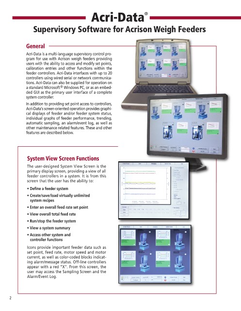
System View Screen Functions
The user-designed System View Screen is the
primary display screen, providing a view of all
feeder controllers in a system. It is from this
screen that the user has the ability to:
• Define a feeder system
• Create/save/load virtually unlimited
system recipes
• Enter an overall feed rate set point
• View overall total feed rate
• Run/stop the feeder system
• View a system summary
• Access other system and
controller functions
Icons provide important feeder data such as
set point, feed rate, motor speed and motor
current, as well as color-coded blocks indicat-
ing alarm/message status. Off-line controllers
appear with a red "X". From this screen, the
user may access the Sampling Screen and the
Alarm/Event Log.
2