
Page 621 - UK Air Operations Regulations (Consolidated) 201121
P. 621
~ Regulation NCC - ANNEX VI - Non-Commercial Complex Operations n trik
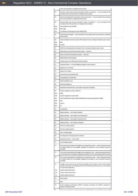
where the pa rameter is displayed electronically
42 Selected vertical speed (all pilot selectable modes of operation) - to be recorded for the
aeroplane where the parameter is displayed electronically
43 Selected heading {al l pilot selectable modes of operation) -to be recorded for the aeroplane
where the parameter is displayed electronically
44 Selected fl ight path (all pilot selectable modes of operation) - to be recorded for the
aeroplane whe re the parameter is displayed electronically:
44a Course/desired track (DSTRK)
44b Path angle
44c Coordinates of final approach path (IRNAV/IAN)
45 Selected decision height - to be recorded for the aeroplane where the parameter is displayed
electroniG1lly
46 Electronic flight instrument system (EFIS) di.splay format, showing the display system status:
46a Pilot
46b Co-pilot
47 Multi-function/engine/ alerts di.splay format, showing the display system status
48 Attemating current (AC) electrical bus starus - each bus
49 Direct current (DC) electrical bus status - each bus
50 Engine bleed valve(,) position
51 Auxiliary power unit (APU) bleed valve(s) position
52 Computer failure - all critical flight and engine control systems
53 Engine thrust command
54 Engine thrust target
55 Computed centre of gravity (CG)
56 Fuel quantity in CG t rim tank
57 Head--t1p display in use
58 Paravisual display on
59 Operational stall protection, stick shaker and pusher activation
60 Pri mary navigation system reference:
60a GNSS
60b lraertial navigational system (INS)
60c VH F omnidirectional radio range {VOR)/d istarace measuring equipment (DME)
60d Ml.S
60e Loran C
60f ll.S
61 Ice detection
62 Engine warning - each engine vibration
63 Engine warning - each engine over temperatu re
64 Engine warning - each engine oil pressure low
65 Engine warning - each engine overspeed
66 Yaw trim surface position
67 Roll trim surface position
68 Yaw or sideslip angle
69 De-icing and/or antHcing systems selection
70 Hydraulic pressu re - each system
71 Loss of cabin pressu re
72 Trim control input position ill the flight crew compartment, pitch - when medianical means
for control inputs are not available, displayed trim position or trim command should be
recorded.
73 Trim control input position in the flight crew compartment, rol I - when mechanical means for
control inputs are not available, displayed trim position or trim commat1d shoo Id be recorded.
74 Trim control input position in the flight crew compartment, yaw - when mechanica l means
for control inputs are not available, displayed trim position or trim command should be
recorded.
75 All flight control input forces (for fly-by-wire flight control systems, where control surface
position is a function of the displacement of the control input device only, it is not necessary
to record thi.s parameter):
75a Control wheel input forces
75b Control column input forces
75c Rudder p edal input forces
76 E vent marker
77 Date
78 Actual navigation performanc·e (ANP) or estimate of posrtion error (EPE) or estimate of
position uncertainty (EPU)
70 r~ h in n.-.. cc:, ,r,. ~ll'iT-, ,...i., - fnr ~.,r.nnl.::inQ"!: tvn.. r .. .-t-ifi<UI h<>f,v-,. 1 bn, ,::.~ -,n-,~ ,,.., ..,,. r..rn.rrt.:ul
20th November 2021 621 of 856