
Page 643 - UK Air Operations Regulations (Consolidated) 201121
P. 643
~ Regulation NCC - ANNEX VI - Non-Commercial Complex Operations n trik
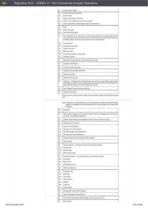
9 Power on each engine:
9a Free power turbine speed (N:F)
9b Engine torque
9c Engine gas generator speed (NG)
9d Right crew companment power control position
9e Other parameter s to enable engine power to be determined
10 Rotor:
10a Main rotor speed
10b Rotor brake (if installed}
11 Primary flight controls - pilot input or control output position if it is possible to derive either
the control input or the control movement (ooe from the other) for all modes of operation
and fli.ght regimes. Otherwise, pilot input and control output posrtion
l la Collective pitch
llb Longitudina I cyclic pitch
ll c Lateral cycl ic pitch
ll d Tail rotor pedal
lle Controllable stabilator (if applicable)
111 Hydraulic selection
12 Hydraulics low pressure (each system should be recorded)
13 Outside air temperature
18 Yaw rate or yaw acceleration
20 Longitudina t acceleration ( body axis)
11 Lateral acceleration
15 Mark.er beacon passage
26 Warn ings - iocluding master mming., gearbox low oil pressure and stability augment:ati-On
svstem failure, and other 'redJ warnings wtiere the warn ing condition cannot be determined
f rom other parameters or from the cockpit voice recorder
27 Each navigation receiver frequency selection
37 Engine control modes
The number in the left-hand column reflects the serial numbers depicted in EUROCAE Document
112A.
Table 2: Helicopters for whidt the data source for the para.met er is either used bv the helicopter
systems or is available on the Instrument panel for use by the flight uew to operate the
helicopter
No' Parameter
14 AFCS mode and engagement status (showing wti idl systems are engaged and which primary
modes are controlling the flight path)
15 Stability augmentation svstem engagement (each S)'stem should be recorded)
16 Main gear box oil pressure
17 Gear box oil temperature:
17a Main gear box oil temperature
17b Intermediate gear box oil temperature
17c Tail rotor gear box oil temperature
19 Indicated sling load force (if signa ls read ily available)
22 Radio altitude
23 Vertical deviation - the approach aid in use should be recorded:
23a IL.S glide path
23b MLS elevation
23c GNSS approach path
24 Horizontal deviation - the approach aid in use should be recorded:
24a IL.S localiser
24b ML.Sazimuth
24c GNSS approach path
28 IJME 1 & 2 distances
19 Navigation data:
19a llriftangle
19b Wind speed
29c Wind direction
19d Latitude
29e Longitude
191 Ground speed
30 Landing gear or gear selector position
31 Engine exhaust gas temperatu re (T4)
32 Turbine in.let temperaru re (TITI/interstage turbine temperaru re (rTTI
33 Fuel contents
20th November 2021 643 of 856