
Page 5 - PBL883 ABB Brochure 3KXA843403R4201 OPERATING INSTRUCTIONS (OI/ACL410-EN) (16PP Q4 STITCH)
P. 5
ACL410 | CHLORINE SENSOR | OI/ACL410-EN PILOT BUILD 5
3 Installation Siting requirements
Install the ALC410 sensor in a clean, dry, well-ventilated location providing easy and safe access for operators to maintain and calibrate the analyzer. The location must also comply with the requirements that follow:
• It must be free of vibrations
• The cell must not be exposed to direct sunlight
• It should be as far as possible from rotating or electrical
communication devices
• The transmitter should be located near to the cell in order
to be able to conduct the periodic calibration
Note .
Install the ACL410 measuring cell at a height that gives easy access during calibration and cleaning. Make sure that there is a clearance of 203 mm (8 in) all around the measuring cell, to allow easy access for removal and maintenance. Refer to Figure 2 for the dimensions of the ACL410 measuring cell.
Figure 2 ACL410 dimensions
Dimensions in mm (in)
203 (8.0) minimum clearance for probe removal
269 (10.60)
194 (7.63)
136 (5.35)
160 (6.30) 143 (5.62)
Sampling requirements
The selection of a good, representative sampling point is important to obtain optimum performance from the analyzer. To reduce sample dead time, locate the analyzer as near to the sampling point as possible. The sample must also conform to
the following conditions:
• Sample flow must be continuous, with a rate between 60 L/h and 75 L/h
• Sample temperature must be between 2 to 50 °C
• Samples must not contain particles exceeding 100 μm in
size. Above these levels, an external filter must be fitted to
the sample lines
• Sample pressure must be more than 0.2 bar and less than
4.0 bar
• Sample must be free of any air bubbles
• Sample must be thoroughly mixed and representative of
Installing the ACL410 measuring cell
Figure 1 identifies the main components of the measuring cell.
1 Attach the measuring cell to the wall with the mounting screws provided, through the designated mounting holes.
2 Install the measuring cell with the No Reagent Feeder option as follows:
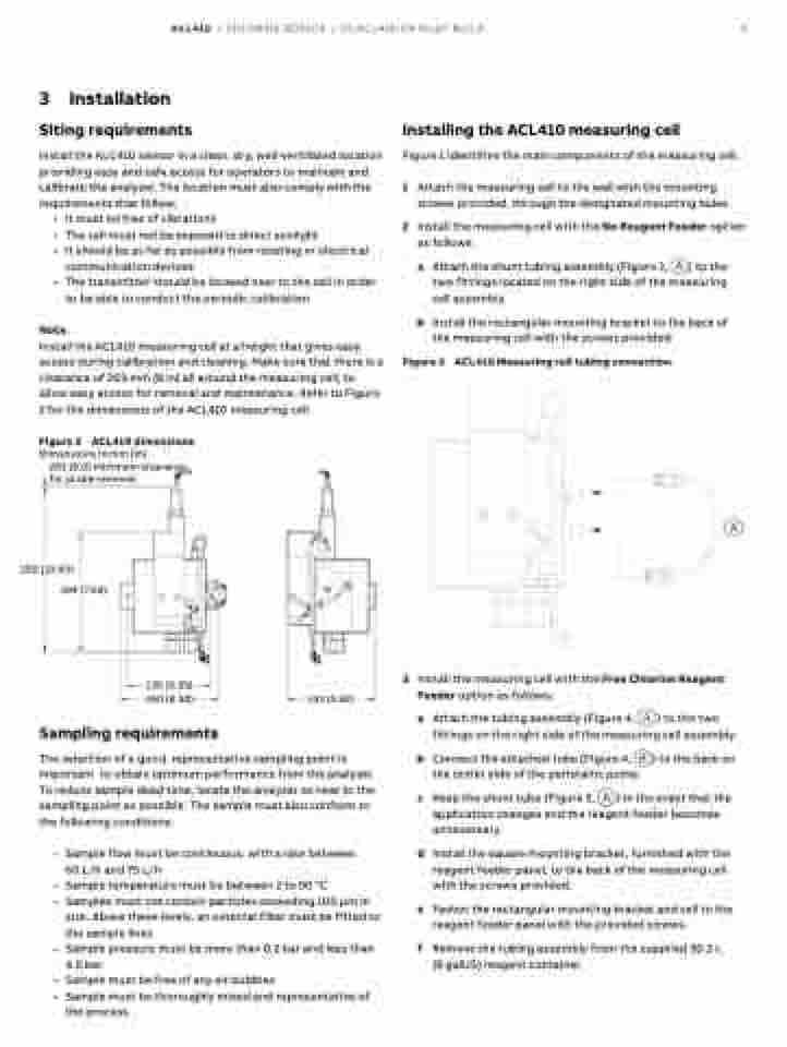
a Attach the shunt tubing assembly (Figure 3, A) to the two fittings located on the right side of the measuring cell assembly.
b Install the rectangular mounting bracket to the back of the measuring cell with the screws provided.
Figure 3
ACL410 Measuring cell tubing connection
A
3 Install the measuring cell with the Free Chlorine Reagent Feeder option as follows:
the process
a Attach the tubing assembly (Figure 4, A) to the two fittings on the right side of the measuring cell assembly.
b Connect the attached tube (Figure 4, B) to the barb on the outlet side of the peristaltic pump.
c Keep the shunt tube (Figure 3, A) in the event that the application changes and the reagent feeder becomes unnecessary.
d Install the square mounting bracket, furnished with the reagent feeder panel, to the back of the measuring cell with the screws provided.
e Fasten the rectangular mounting bracket and cell to the reagent feeder panel with the provided screws.
f Remove the tubing assembly from the supplied 30.2 L (8 galUS) reagent container.
