
Page 7 - PBL883 ABB Brochure 3KXA843403R4201 OPERATING INSTRUCTIONS (OI/ACL410-EN) (16PP Q4 STITCH)
P. 7
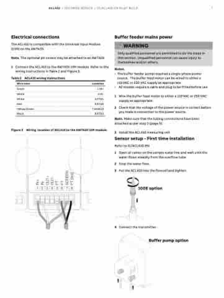
wiring instructions in Table 2 and Figure 5.
Table 2 ACL410 wiring instructions
Wire color
Green
White
White
Red
Yellow/Green
ACL410 | CHLORINE SENSOR | OI/ACL410-EN PILOT BUILD 7
Electrical connections
The ACL410 is compatible with the Universal Input Module (UIM) on the AWT420.
Note . The optional pH sensor may be attached to an AWT420
1 Connect the ACL410 to the AWT420 UIM module. Refer to the
Buffer feeder mains power
Notes .
• The buffer feeder pump required a single-phase power source. The buffer feed motor can be wired to either a 110 VAC or 230 VAC supply as appropriate.
• All models require a cable and plug to be fitted before use.
1 Wire the buffer feed motor to either a 110 VAC or 230 VAC supply as appropriate.
2 Check that the voltage of the power source is correct before you make a connection to the power source.
Note . Make sure that the tubing connections have been attached as per step 3 (page 5).
3 Install the ACL410 measuring cell.
Sensor setup - First time installation
Refer to CI/ACL410-EN
1 Open all valves on the sample water line and wait until the water flows steadily from the overflow tube.
2 Stop the water flow.
3 Put the ACL410 into the flowcell and tighten.
100E option
4 Connect the transmitter.
Buffer pump option
 WARNING
 Only qualified personnel are permitted to do the steps in this section. Unqualified personnel can cause injury to themselves and/or others.
       Black
Figure 5
Location
1 IN+
2 IN-
5 RTD1
6 RTD2
7 SHIELD
8 RTD3
Wiring location of ACL410 to the AWT420 UIM module .
