
Page 6 - PBL883 ABB Brochure 3KXA843403R4201 OPERATING INSTRUCTIONS (OI/ACL410-EN) (16PP Q4 STITCH)
P. 6
6 ACL410 | CHLORINE SENSOR | OI/ACL410-EN PILOT BUILD
...3 Installation
. . .Installing the ALC410 measuring cell
g Insert the weighted end of the tubing assembly into the container and connect the other end to the barb on the inlet side of the peristaltic pump
4 Install the measuring cell with the Total Chlorine Reagent Feeder option as follows:
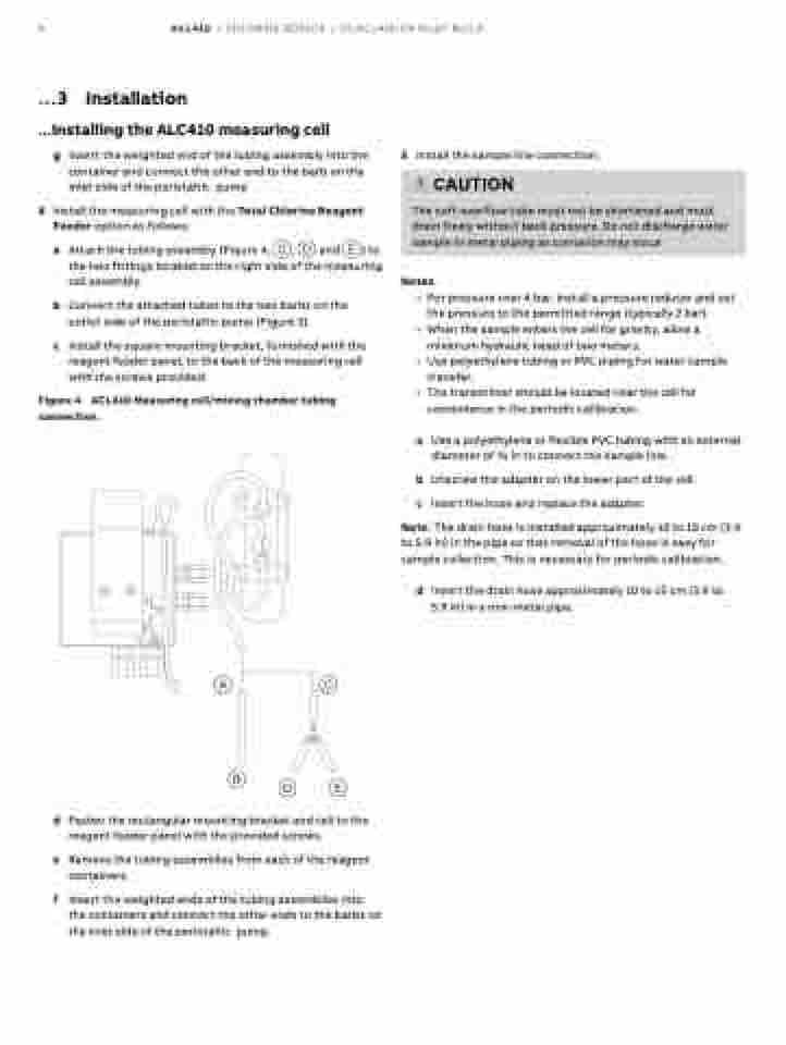
a Attach the tubing assembly (Figure 4, C, D and E) to the two fittings located on the right side of the measuring cell assembly.
b Connect the attached tubes to the two barbs on the outlet side of the peristaltic pump (Figure 3).
c Install the square mounting bracket, furnished with the reagent feeder panel, to the back of the measuring cell with the screws provided.
Figure 4 ACL410 Measuring cell/mixing chamber tubing connection .
5 Install the sample line connection:
Notes.
• For pressure over 4 bar, install a pressure reducer and set
the pressure to the permitted range (typically 2 bar). • When the sample enters the cell for gravity, allow a
minimum hydraulic head of two meters.
• Use polyethylene tubing or PVC piping for water sample
transfer.
• The transmitter should be located near the cell for
convenience in the periodic calibration.
a Use a polyethylene or flexible PVC tubing with an external diameter of 3⁄8 in to connect the sample line.
b Unscrew the adapter on the lower part of the cell.
c Insert the hose and replace the adapter.
Note . The drain hose is installed approximately 10 to 15 cm (3.9 to 5.9 in) in the pipe so that removal of the hose is easy for sample collection. This is necessary for periodic calibration.
d Insert the drain hose approximately 10 to 15 cm (3.9 to 5.9 in) in a non-metal pipe.
CAUTION
The soft overflow tube must not be shortened and must drain freely without back pressure. Do not discharge water sample in metal piping as corrosion may occur
AC
B
d Fasten the rectangular mounting bracket and cell to the reagent feeder panel with the provided screws.
e Remove the tubing assemblies from each of the reagent containers.
f Insert the weighted ends of the tubing assemblies into the containers and connect the other ends to the barbs on the inlet side of the peristaltic pump.
DE
