
Page 190 - Libro 2
P. 190
170
PART 3 — PERIPHERAL ARTERIAL
PATIENT PREPARATION
As with any examination, the procedures should be explained to the patient, taking into consideration the age and mental status of the patient. If relatives or caregivers are present, they can be used to assist with the explanation if necessary.
As noted earlier in this chapter, another consid- eration prior to the beginning of the ultrasound is review of the patient’s operative notes. An opera- tive note provides important information as to the specific course and composition of the bypass graft, which can be used as a guide to facilitate bypass graft imaging.
PATIENT POSITIONING
The patient should be positioned supine with the head of the bed slightly elevated. The limb to be ex- amined should be externally rotated at the hip with the knee slightly bent. In those patients with various joint conditions such as arthritis, a small pillow may be placed under the knee to avoid joint pain. The pa- tient should be resting comfortably for a few minutes prior to the recording of any velocity measurements.
EQUIPMENT
Various transducer frequencies can be used to image bypass grafts. For superficial in situ bypass grafts, a 10- or 12-MHz transducer will provide optimal near- field imaging. For deeper bypass grafts, a 5-7 MHz transducer will be needed. Technologists and sonog- raphers must remember that many of the ultrasound transducers commonly used today have multiple imaging and Doppler frequencies. These can and should be adjusted if the course of the bypass is such that various tissue depths are encountered.
Required Documentation
Individual laboratory protocols vary slightly; how- ever, there are several essential elements that need to be documented. The following lists the minimum suggested documentation; however, additional imag- es are often necessary. Grayscale images should be recorded of the inflow artery, proximal anastomosis, mid-graft, distal anastomosis, and outflow artery. At each of these locations, a spectral Doppler waveform should also be recorded with the peak systolic veloc- ity (PSV) measured. If color flow imaging is part of the protocol, color flow images should be document- ed at the same sites. In the case of any abnormali- ties, additional documentation in grayscale, spectral Doppler, and color should be recorded. For any ste- notic areas, spectral Doppler needs to be noted prior
to the stenotic region, at the area of greatest velocity shift, and distal to the stenotic region.
These requirements are based on current stan- dards established by the Intersocietal Commission for the Accreditation of Vascular Laboratories (ICAVL).
SCANNING TECHNIQUE
The examination should begin with the selection of the appropriate transducer based on body habitus and bypass depth. The ultrasound system applica- tion preset for peripheral arterial imaging should be chosen. The application preset settings for grayscale, spectral Doppler, and color will likely need to be spe- cifically optimized for each patient.
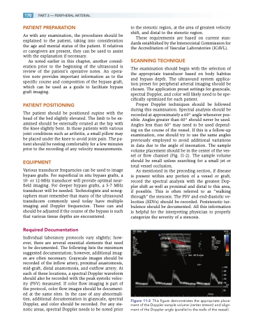
Proper Doppler techniques should be followed during this examination. Spectral analysis should be recorded at approximately a 60° angle whenever pos- sible. Angles greater than 60° should never be used. Angles less than 60° may need to be used depend- ing on the course of the vessel. If this is a follow-up examination, one should try to use the same angles previously employed to avoid additional variations in data due to the angle of insonation. The sample volume placement should be in the center of the ves- sel or flow channel (Fig. 11-2). The sample volume should be small unless searching for a small jet or total vessel occlusion.
As mentioned in the preceding section, if disease is present within any portion of a vessel or graft, record the spectral analysis with the greatest Dop- pler shift as well as proximal and distal to this area, if possible. This is often referred to as “walking through” the stenosis. The PSV and end-diastolic ve- locities (EDVs) should be recorded. Poststenotic tur- bulence should be documented. All this information is helpful for the interpreting physician to properly categorize the severity of a stenosis.
Figure 11-2 This figure demonstrates the appropriate place- ment of the Doppler sample volume (center stream) and align- ment of the Doppler angle (parallel to the walls of the vessel).
