
Page 86 - Libro vascular I
P. 86
Chap-07.qxd 29~8~04 14:42 Page 77
OPTIMIZING THE SCAN
77
AC
True object
BD
Strongly reflecting interface
Ghost object
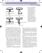
Figure 7.1 Imaging artefacts can be produced by multiple reflections from strongly reflecting surfaces. The solid line shows the true path of the ultrasound beam. The dashed lines show the path of the beam assumed by the ultrasound scanner and the assumed interfaces displayed on the ultrasound images. A: Multiple reflections between the transducer and a strongly reflecting boundary. B: Multiple reflections between two parallel, strongly reflecting surfaces. C: Multiple reflections not returning along the same path. D: Mirror image produced in the presence of a strongly reflecting surface.
tissue being investigated. This can be due to a fea- ture being misplaced on the image, a feature appearing that is not present within the tissue or an existing structure that is absent from the image. The creation of an image relies on the assumption that the ultrasound beam travels in a straight path between the transducer and the structures within the tissue and returns along the same path once reflected. It is also assumed that the attenuation of tissue is constant. Any process that alters this situ- ation can lead to the misplacement or absence of information. This can be caused by the following:
● Multiple reflections can lead to reverberation artifacts, seen as several equidistant echoes that reduce in brightness with depth. This is due to multiple reflections, along the same path, between the transducer and a strongly reflecting boundary (Fig. 7.1A) or between two parallel, strongly reflecting surfaces (Fig. 7.1B). If the multiple reflections do not return along the same path, the structure may be misplaced on the image (Fig. 7.1C).
● A mirror image of a structure can be produced in the presence of a strongly reflecting surface.
Figure 7.1D shows how the true position of a structure is displayed, with a second ghost image also displayed. The ghost image has been detec- ted by an ultrasound beam that has undergone multiple reflection from the strongly reflecting surface.
● Refraction can lead to bending of the path of the ultrasound when the beam passes through an interface between two media in which the speed of sound is significantly different (see Fig. 2.7).
● Range ambiguity can occur if an echo from the previously transmitted pulse is received back from a distant boundary after the current ultra- sound pulse has been transmitted. The scanner will assume that the echo is from the current pulse and place it nearer to the top of the image rather than at its true depth.
● Grating lobes are areas of lower intensity ultra- sound outside the main beam and are produced as a function of the multi-element structure of array transducers. These grating lobes can lead to strongly reflecting surfaces outside the main beam being displayed in the image.
