
Page 87 - Libro vascular I
P. 87
Chap-07.qxd 29~8~04 14:42 Page 78
78
PERIPHERAL VASCULAR ULTRASOUND
the tissue at depth may appear as different levels of gray, despite having similar backscatter properties (Fig. 7.3). For example, the tissue beneath a low- attenuation, anechoic region, such as a cyst, may appear brighter than adjacent areas. Highly atten- uating tissue, however, such as calcified plaque, can cause loss of ultrasound information beneath the region, leading to a shadow (see Fig. 9.12).
COLOR DOPPLER CONTROLS
Color pulse repetition frequency
The pulse repetition frequency (PRF) should be adjusted to optimize the image of the blood flow in the vessel under examination. Many duplex sys- tems display the value of the PRF in Hz. However, some systems only indicate the PRF as a mean veloc- ity on the color bar, in cm/s, or specify the sam- pling rate as high-, medium- or low-velocity flow. The examination preset selects a nominal PRF to start a specific examination. The PRF is generally set moderately high for sampling normal arterial flow, typically a PRF of 3000–4000 Hz, so that the peak systolic phase of the cardiac cycle appears in the upper portion of the color scale without alias- ing, as demonstrated in Figure 4.9B. If the PRF is set too low, aliasing will be demonstrated in a normal vessel during the peak systolic phase, mak- ing it more difficult to identify areas of true flow disturbance. If the PRF is set too high, the peak systolic phase of the cardiac cycle will appear in the lower region of the color scale, flow changes will be less well differentiated on the image and minor flow disturbances could be overlooked. Low-velocity flow in diastole may also go undetected.
In situations in which there is significant pathol- ogy, the flow velocities may be much lower than normal. For example, the flow velocities in a calf artery distal to a long superficial femoral and popliteal artery occlusion may be very low. Using a default PRF setting of 3000 Hz may not adequately demonstrate the low-velocity flow in the patent calf artery because the sampling rate is too high (Fig. 7.4). The PRF should be lowered to demonstrate the low-velocity flow, showing the systolic phase in the upper part of the color scale (Fig. 7.4C). An alternative technique to altering the PRF to opti- mize the flow display is to change the position of
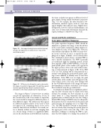
Figure 7.2 An image showing how an artefact (arrow) can give the impression of a dissection or tear, of the carotid artery wall.
Figure 7.3 Differences in attenuation can be observed in this image of a synthetic bypass graft. The graft has spaced external supporting rings that are causing increased attenuation in the tissue lying below the rings (arrows).
The image in Figure 7.2 shows how an artifact can give the appearance of a dissection, or tear, of the carotid artery wall. If an artifact is suspected, the vessel should be imaged in different planes or from different angles. The artifact may then appear in a different position relative to the vessel or may not appear at all, confirming that it is not a true structure that has been visualized. It is usually eas- ier to identify artifacts in real-time imaging than on a frozen image. If there is a significant differ- ence in the attenuation seen by different scan lines,
