
Page 89 - Libro vascular I
P. 89
Chap-07.qxd 29~8~04 14:42 Page 80
80
PERIPHERAL VASCULAR ULTRASOUND
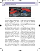
Figure 7.5 Images of a carotid artery showing how a vessel may need to be imaged with the color box steered in more than one direction to demonstrate flow in the whole vessel.
This is less of a problem in modern duplex systems. As the time taken to produce an image lengthens, especially when imaging with a large color box or at depth, a time delay may be introduced between the signals detected from different sides of the image. This can result in the color image displaying flow detected at different parts of the cardiac cycle. For example, both end diastolic and peak systolic flow in a vessel may be displayed on different sides of the image. Many systems have a control for increasing the color sensitivity, which increases the number of pulses sent down each scan line. This can improve the color image but decreases the overall frame rate. In certain situations, pulsatile low-volume flow in a vessel may be seen as a brief flash of color on the image, and it may be difficult to follow the vessel. Increasing the color persistence will display the color in the vessel for a longer period of time and can make the vessel easier to follow. The color write priority control can be adjusted to write color on an image where a high B-mode gain is necessary (see below).
COLOR IMAGING ARTIFACTS
Color flow imaging artifacts can lead to failure to display flow when, in fact, it is present, as shown in Figure 7.5. A bright black and white imaging arti- fact (as seen in Fig. 7.2) may be displayed in pref- erence to the color flow information, and this may give the appearance of a structure within the vessel lumen, around which the flow is displayed. If the
color write priority is set too low in the presence of a noisy black and white image, flow detected may not be displayed due to the lack of a clear vessel lumen. Giving priority to the color flow imaging means that the B-mode image can be rea- sonably bright without losing color information on the screen.
A strongly reflective surface can lead to the loss of ultrasound signals beyond the interface. For example, calcification within the vessel wall or the presence of bowel gas can produce shadowing on both the black and white image and color flow image and will prevent spectral Doppler recordings (see Fig. 8.26).
Artifacts can also be introduced into the color image whereby color is displayed when blood flow is not present. This can occur when the color gain is set too high, giving the appearance of the color ‘bleeding’ out of the vessel (Fig. 7.6). Alterna- tively, anechoic areas can be filled with speckled color due to noise, if the gain is set high or if there is low-velocity tissue motion present (e.g., due to respiration). Tissue bruits (e.g., near a stenosis) may result in color appearing outside the vessel wall (see Fig. 11.18A).
Multiple reflection can produce color image artifacts. Figure 7.7 shows a mirror image of the subclavian artery produced by multiple reflections from the pleura overlying the lung. This mirror image artifact can be seen where a vessel overlies a strongly reflecting surface, such as the tissue–air interface present at the pleura. The tibial vessels or
