
Page 90 - Libro vascular I
P. 90
Chap-07.qxd 29~8~04 14:42 Page 81
OPTIMIZING THE SCAN
81
and displayed for the mirror image may not be the same as for the vessel itself. The artifactual Doppler signal displayed on the color image can also be detected with spectral Doppler, if the sample volume is placed over the mirror image.
The color image may not give a true representa- tion of the relative blood velocities within the ves- sel. Changes in the angle of insonation, owing to changes in vessel direction, can lead to color imag- ing artifacts, giving the false impression of changes in blood velocity (see Fig. 4.7). Aliasing artifacts will also change the appearance of the color image (see Figs 4.9A and 4.11).
SPECTRAL DOPPLER OPTIMIZATION
The spectral Doppler PRF should be set to avoid aliasing and the high-pass filter should be set to remove wall thump but not useful Doppler signals. The spectral Doppler PRF may be referred to as ‘scale’ or ‘flow rate’ on some systems. The selection of the size of the sample volume is an important consideration. If detailed investigation of flow within a stenosis is to be performed, a small sample volume is required. The sample volume should be placed in the center of the vessel or at the point of maximum velocity indicated by the color image. However, if the presence of flow within a vein is to be detected, a large sample volume may be more appropriate. The issue of spectral Doppler angle cor- rection remains a contentious subject. Some units insist that all measurements be taken with the cursor lined up with the direction of flow at a fixed angle of 60° whereas other departments use the smallest angle of insonation possible (see Ch. 6). In practice, the decision on which technique to use may be dic- tated by local protocols. The position of the angle correction cursor should be carefully lined up with the vessel wall, or the direction of blood flow, to minimize angle-related errors. There are three pos- sible reasons why a Doppler signal may be displayed both above and below the baseline, and the sonog- rapher should be able to identify these:
● aliasing (see Fig. 3.14A)
● mirroring due to the gain being set too high
(see Fig. 6.3)
● flow reversal during the cardiac cycle (see
Fig. 5.8).
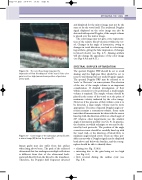
Figure 7.6 The color flow image may give the impression of flow ‘bleeding out’ of the vessel if the color gain is set too high (arrow shows position of posterior artery wall).
S
M
P
Figure 7.7 Color image of the subclavian artery (S) with a mirror image (M) below the pleura (P).
bypass grafts may also suffer from this artifact when lying above bone. The path of the reflected ultrasound that has undergone multiple reflections is different from that of the ultrasound back- scattered directly from the blood to the transducer. Therefore, the Doppler shift frequency detected
