
Page 99 - Libro vascular I
P. 99
Chap-08.qxd 1~9~04 16:41 Page 90
90
PERIPHERAL VASCULAR ULTRASOUND
Muscle
CCA
Muscle
AB
Figure 8.5
Transverse B-mode images. A: CCA and jugular vein. B: The ICA and ECA just above the carotid bifurcation.
VEIN
ICA
VEIN
ECA
Figure 8.6
C
ICA
ECA
CCA
B A
Longitudinal scan planes used to visualize the carotid arteries. A: Posterior. B: Lateral. C: Anterior.
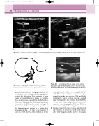
Figure 8.7
Longitudinal B-mode image of the carotid bifurcation with the ICA and ECA seen in the same plane. The arrows mark where the intima-media layer can be seen.
same plane and will have to be imaged individ- ually. This is achieved by keeping the lower por- tion of the probe face over the CCA and slowly rotating the upper portion through a small angle to image first the ICA and then the ECA, or vice versa. Only small probe movements are required when imaging the ICA and ECA, as the vessels usually lie close together.
3. Having located the three vessels and observed any evidence of disease in the B-mode image, color flow imaging can be used to investigate
gained from transverse imaging is helpful for locating the correct longitudinal imaging plane to view the bifurcation. It is necessary to use a range of longitudinal scan planes to visualize the carotid arteries, especially at the bifurcation (Fig. 8.6). Typically, the ICA lies posterolateral or lateral to the ECA and is usually the larger of the two vessels. In a small percentage of cases, the bifurcation will appear as a tuning fork arrangement (Fig. 8.7), but in the majority of cases the ECA and ICA will not be seen in the
