
Page 190 - Hydra-matic 6 Speed RWD Technician's Guide (October 2005)
P. 190
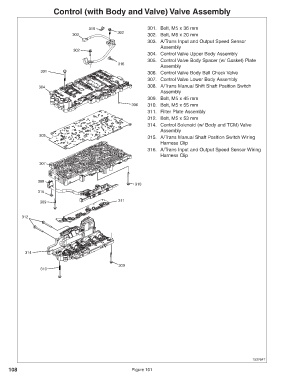
Control (with Body and Valve) Valve Assembly


                                      316                      301. Bolt, M5 x 36 mm
                                                  302
                               303                             302. Bolt, M6 x 20 mm
                                                               303. A/Trans Input and Output Speed Sensor
                                                                    Assembly
                                302
                                                               304. Control Valve Upper Body Assembly
                                                               305. Control Valve Body Spacer (w/ Gasket) Plate
                                                  316
                                                                    Assembly
                  301
                                                               306. Control Valve Body Ball Check Valve
                                                               307. Control Valve Lower Body Assembly
                 304                                           308. A/Trans Manual Shift Shaft Position Switch
                                                                    Assembly
                                                               309. Bolt, M5 x 45 mm
                                                        306    310. Bolt, M5 x 55 mm
                                                               311. Filter Plate Assembly
                                                               312. Bolt, M5 x 53 mm
                                                               314. Control Solenoid (w/ Body and TCM) Valve
                                                                    Assembly
                 305
                                                               315. A/Trans Manual Shaft Position Switch Wiring
                                                                    Harness Clip
                                                               316. A/Trans Input and Output Speed Sensor Wiring
                                                                    Harness Clip
                 307


                 308
                                                         310
                 315
                                                  311
                  309

          312


            314


                                                   309
                  310


                                                                                                          1537647

     108                                                Figure 101