
Page 15 - Programmable Logic Controllers, Fifth Edition
P. 15
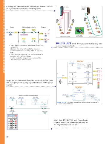
Coverage of communications and control networks utilizes
Scanner
clear graphics to demonstrate how things work I/O Module DeviceNet
Module
Input Ladder logic program Outputs
L1 I:1/3 O:2/5 L2
I:1/3 O:2/5
OFF Force> ON 4-wire cable
ON
Conventional system and connector DeviceNet system
O:2/5 O:2/6 O:2/6 M
ON
BULLETED LISTS break down processes to helpfully sum-
• The processor ignores the actual state of input limit marize execution of tasks
switch I:1/3.
• Although limit switch I:1/3 is o (0 or false) the
processor considers it as being in the on (1 or true)
state.
• The program scan records this, and the program is
executed with this forced status.
• In other words, the program is executed as if the
limit switch were actually closed.
Ladder logic
Timer_Sw
<Local:1:I.Data.6>
TON
Timer On Delay EN
Timer Status_Timer
Preset 10000 DN
Accum 0 Outputs L2
EN_PL EN_PL
Status_Timer.EN <Local:2:O.Data.1>
L1
Input TT_PL
TT_PL
Status_Timer.TT <Local:2:O.Data.2>
Timer_Sw
DN_PL
Diagrams, such as this one illustrating an overview of the func- DN_PL
tion block programming language, help students put the pieces Status_Timer.DN <Local:2:O.Data.3>
together
FBD equivalent
TONR_01
TONR ...
Timer On Delay with Reset
0 0
Timer_Sw TimerEnable ACC ACC_Value
Operation of the program can be viewed in real time 10000 0
10000 PRE EN EN_PL
Motor_Stop Motor_Start Track_Motor 0 TT_PL
<Local:1:I.Data.0> <Local:1:I.Data.1> <Local:2:O.Data.0> TT
Reset 0
DN DN_PL
Track_Motor Enter_LS
<Local:2:O.Data.0> <Local:1:I.Data.2> Wash_In_Use Figure 15-110 Comparison between ladder logic and the FBD equivalent for a
L 10 second TON and TONR timer.
Do_Not_Enter_Sign
Wash_In_Use <Local:2:O.Data.1> • When the Motor_Stop button is opened the output • Opening the Timer_Sw resets all outputs as well as
of the BAND block turns false to de-energize the the accumulated value to zero.
Exit_LS contactor coil and stop the motor.
<Local:1:I.Data.3> Wash_In_Use • The timer can also be reset by way of the Reset
U input.
Figure 15-110 shows a comparison between ladder
logic and the FBD equivalent for the 10 second TON (on- Figure 15-111 shows a comparison between ladder logic
delay timer) and TONR (on-delay with reset). The opera- and the FBD equivalent for the Up/Down counter used to
Discrete I/O
tion of the FBD can be summarized as follows: limit the number of parts stored in a buffer zone to 50. The
Slot 1 Slot 2 More than 175 SLC-500 and ControlLogix
operation of the FBD can be summarized as follows:
• When the Timer_Sw is closed, the TONR func-
00 00
program simulation videos tie
tion block timer turns true and starts accumulating d directly to
• The CTUD up/down counter function block accu-
01 01
time. the programs studied in the text mulated value is initially reset by momentary actua-
02 02 tion of the Restart_Button.
• The accumulated time is monitored by the output
03 03 reference tag named ACC. • The accumulated count is monitored by the output
• The EN (enable bit) output changes to 1 to turn on reference tag named ACC.
the EN_PL. • Each time a part enters the buffer zone, the Enter_
• The TT (timer timing bit) output changes to 1 to Limit_Sw is actuated and the CUEnable input turns
turn on the TT_PL. true to increment the count by 1.
xiv • The timer times out after 10 seconds to set the DN • Each time a part exits the buffer zone, the Exit_
(done bit) to 1 and turn on the DN_PL and reset the Limit_Sw is actuated and the CDEnable input turns
TT bit to zero and turn off the TT_PL. true to decrement the count by 1.
• The EN bit and EN_PL remain on as long as the • Whenever the number of parts in the buffer zone
Timer_Sw stays toggled closed. reaches 50 the DN bit is set to 1 and the output of
pet73842_fm_i-xviii.indd 14 05/11/15 4:15 PM
Function Block Programming Part 6 391