Page 91 - Programmable Logic Controllers, Fifth Edition
P. 91

CHAPTER 4 REVIEW QUESTIONS

                                                                                 __
                 1. Explain the binary principle.                         e. Y =    A B + C  __
                 2. What is a logic gate?                                 f.  Y =(ABC + D)(E   F )
                 3. Draw the logic symbol, construct a truth table, and   7. State the logic instruction you would use when you
                    state the Boolean equation for each of the            want to:
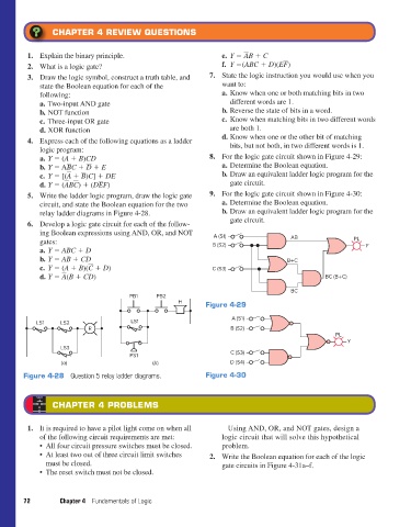
                    following:                                            a. Know when one or both matching bits in two
                    a. Two-input AND gate                                    different words are 1.
                    b. NOT function                                       b. Reverse the state of bits in a word.
                    c. Three-input OR gate                                c. Know when matching bits in two different words
                    d. XOR function                                          are both 1.
                 4. Express each of the following equations as a ladder   d. Know when one or the other bit of matching
                    logic program:                                           bits, but not both, in two different words is 1.
                    a. Y = (A + B)CD                                   8. For the logic gate circuit shown in Figure 4-29:
                            __
                                  __
                    b. Y = A   B C +    D  + E                            a. Determine the Boolean equation.
                            __
                                __
                    c. Y = [(   A  +    B )C] + DE                        b. Draw an equivalent ladder logic program for the
                           __ __
                                      __
                    d. Y = (   A B   C ) + (D   E F)                         gate circuit.
                 5. Write the ladder logic program, draw the logic gate   9. For the logic gate circuit shown in Figure 4-30:
                    circuit, and state the Boolean equation for the two   a. Determine the Boolean equation.
                    relay ladder diagrams in Figure 4-28.                 b. Draw an equivalent ladder logic program for the
                 6. Develop a logic gate circuit for each of the follow-     gate circuit.
                    ing Boolean expressions using AND, OR, and NOT      A (S1)
                    gates:                                             B (S2)                  AB                PL
                    a. Y = ABC + D                                                                                   Y
                    b. Y = AB + CD __                                                         B+C
                    c. Y = (A + B)(   C  + D)                          C (S3)
                           __
                    d. Y =    A (B + CD)                                                                 BC (B+C)

                                                                                               BC
                                               PB1     PB2
                                                             H       Figure 4-29

                                                                             A (S1)
                   LS1    LS2                  LS1
                                   R                                         B (S2)
                                                                                                            PL
                                                                                                               Y
                          LS3
                                               PS1                           C (S3)
                           (a)                        (b)                    D (S4)
               Figure 4-28  Question 5 relay ladder diagrams.        Figure 4-30


                        CHAPTER 4 PROBLEMS


                 1. It is required to have a pilot light come on when all     Using AND, OR, and NOT gates, design a
                    of the following circuit requirements are met:        logic circuit that will solve this hypothetical
                    •  All four circuit pressure switches must be closed.  problem.
                    •  At least two out of three circuit limit switches   2. Write the Boolean equation for each of the logic
                      must be closed.                                     gate circuits in Figure 4-31a–f.
                    •  The reset switch must not be closed.


               72         Chapter 4  Fundamentals of Logic


          pet73842_ch04_061-073.indd   72                                                                               03/11/15   3:52 PM
   86   87   88   89   90   91   92   93   94   95   96