
Page 16 - Programmable Logic Controllers, Fifth Edition - Mobile version
P. 16
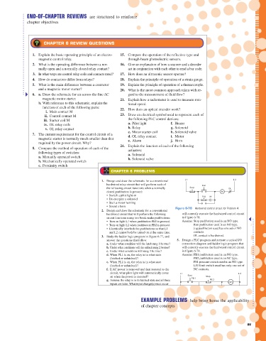
END-OF-CHAPTER REVIEWS are structured to reinforce
chapter objectives
CHAPTER 6 REVIEW QUESTIONS
1. Explain the basic operating principle of an electro- 15. Compare the operation of the reflective-type and
magnetic control relay. through-beam photoelectric sensors.
2. What is the operating difference between a nor- 16. Give an explanation of how a scanner and a decoder
mally open and a normally closed relay contact? act in conjunction with each other to read a bar code.
3. In what ways are control relay coils and contacts rated? 17. How does an ultrasonic sensor operate?
4. How do contactors differ from relays? 18. Explain the principle of operation of a strain gauge.
5. What is the main difference between a contactor 19. Explain the principle of operation of a thermocouple.
and a magnetic motor starter? 20. What is the most common approach taken with re-
6. a. Draw the schematic for an across-the-line AC gard to the measurement of fluid flow?
magnetic motor starter. 21. Explain how a tachometer is used to measure rota-
b. With reference to this schematic, explain the tional speed.
function of each of the following parts: 22. How does an optical encoder work?
i. Main contact M
ii. Control contact M 23. Draw an electrical symbol used to represent each of
iii. Starter coil M the following PLC control devices:
iv. OL relay coils a. Pilot light f. Heater
v. OL relay contact b. Relay g. Solenoid
7. The current requirement for the control circuit of a c. Motor starter coil h. Solenoid valve
d. OL relay contact
i. Motor
magnetic starter is normally much smaller than that e. Alarm j. Horn
required by the power circuit. Why?
8. Compare the method of operation of each of the 24. Explain the function of each of the following
actuators:
following types of switches: a. Solenoid
a. Manually operated switch b. Solenoid valve
b. Mechanically operated switch c. Stepper motor
c. Proximity switch
25. Compare the operation of open-loop and closed-
9. What do the abbreviations NO and NC represent CHAPTER 6 PROBLEMS
loop control.
when used to describe switch contacts?
26. What is a seal-in circuit?
10. Draw the electrical symbol used to represent each L 1 L2
1. Design and draw the schematic for a conventional
27. In what way is the construction and operation of an
of the following switches: hardwired relay circuit that will perform each of Run
electromechanical latching relay different from a
a. NO pushbutton switch the following circuit functions when a normally Stop OL
standard relay?
b. NC pushbutton switch closed pushbutton is pressed: M
• Switch a pilot light on
28. Give a short description of each of the following
c. Break-make pushbutton switch • De-energize a solenoid Jog M
control processes:
d. Three-position selector switch • Start a motor running
e. NO limit switch • Sound a horn a. Sequential Figure 6-78 Hardwired control circuit for Problem 4.
b. Combination
f. NC temperature switch 2. Design and draw the schematic for a conventional
c. Automatic
g. NO pressure switch hardwired circuit that will perform the following will correctly execute the hardwired control circuit
in Figure 6-78.
h. NC level switch circuit functions using two break-make pushbuttons: Assume: Stop pushbutton used is an NO type.
29. Compare the type of sensor signal obtained from a
• Turn on light L1 when pushbutton PB1 is pressed.
i. NO proximity switch • Turn on light L2 when pushbutton PB2 is pressed. Run pushbutton used is an NO type.
thermocouple with that from an RTD.
11. Outline the method used to actuate inductive and Electrically interlock the pushbuttons so that L1 Jog pushbutton used has one set of NO
•
30. Explain how a magnetic reed float switch works.
capacitive proximity sensors. and L2 cannot both be turned on at the same time. contacts.
31. What is the function of an electrical interlocking
3. Study the ladder logic program in Figure 6-77, and OL contact is hardwired.
12. How are reed switch sensors actuated? answer the questions that follow: 5. Design a PLC program and prepare a typical I/O
circuit?
a.
13. Compare the operation of a photovoltaic solar cell Under what condition will the latch rung 1 be true? connection diagram and ladder logic program that
32. What is the role of instrumentation in an industrial
with that of a photoconductive cell. b. Under what conditions will the unlatch rung 2 be true? will correctly execute the hardwired control circuit
process?
c. Under what condition will rung 3 be true? in Figure 6-79.
14. What are the two basic components of a photoelec- 33. You have been assigned the task of calibrating an
d. When PL1 is on, the relay is in what state
Assume: PB1 pushbutton used is an NO type.
tric sensor? (latched or unlatched)? PB2 pushbutton used is an NC type.
instrument. How would you proceed?
e. When PL2 is on, the relay is in what state PS1 pressure switch used is an NO type.
(latched or unlatched)? LS1 limit switch used has only one set of
f. If AC power is removed and then restored to the NC contacts.
circuit, what pilot light will automatically come
128 Chapter 6 Developing Fundamental PLC Wiring Diagrams and Ladder Logic Programs L1 L 2
on when the power is restored? Start PB 1 Stop
g. Assume the relay is in its latched state and all three PB 2 CR1
inputs are false. What input change(s) must occur
for the relay to switch into its unlatched state?
h. If the examine if closed instructions at addresses PL1
I/1, I/2, and I/3 are all true, what state will the CR1-1
relay remain in (latched or unlatched)?
EXAMPLE PROBLEMS help bring home the applicability
4. Design a PLC program and prepare a typical I/O CR1-2 SOL 1
of chapter concepts
connection diagram and ladder logic program that
PS1
Inputs Ladder logic program Outputs CR2
L1 L2
I/1 I/1 I/2 O/9 LS1 CR2-1 SOL 2 xv
Rung 1 L O/9 PL1
SS1
I/2 I/3 O/9 CR2-2 SOL 3
Rung 2 U
O/10 PL2
I/3 O/9 O/10
Rung 3 PL2
pet73842_fm_i-xviii.indd 15 Figure 6-77 Ladder logic program for Problem 3. Figure 6-79 Hardwired control circuit for Problem 5. 05/11/15 4:15 PM
Developing Fundamental PLC Wiring Diagrams and Ladder Logic Programs Chapter 6 129