
Page 286 - Programmable Logic Controllers, Fifth Edition - Mobile version
P. 286
Bit address—Is the address of the source bit. The instruc-
tion inserts the status of this bit in either the first (lowest) L1 Inputs LS Ladder logic program
bit position (for the BSL instruction) or the last (highest) Limit switch BSL
BIT SHIFT LEFT
bit position (for the BSR instruction) in the array. LS File #B3:10 EN
Length—Indicates the number of bits to be shifted, Sensor Control R6:0 DN
or the file length, in bits. The status bits of the con- Bit address Ι:1/1
Length
20
trol word are the enable, done, error, and unload bits. Ι:1/1
Their functions can be summarized as follows:
- Enable Bit (EN)—The enable bit follows the instruc-
tions status and is set to 1 when the instruction is true. B3:Table - Before limit switch clock pulse
- Done Bit (DN)—The done bit is set to 1 when the
instruction has shifted all bits in the file one posi- B3:10 15 14 13 12 11 10 9 8 7 6 5 4 3 2 1 0
tion. It resets to 0 when the instruction goes false. B3:11 1 0 1 0 0 0 1 0 1 0 0 0 1 1 0 1 0 1 0 0 0
1 1 1 0
0 0 0
0
0
0 0
- Error Bit (ER)—The error bit is set to 1 when the
instruction has detected an error, which can happen Bit address
when a negative number is entered in the length. I:1/1
- Unload Bit (UL)—The unload bit’s status is con- Shift direction 1
trolled by shifting of the last bit of the file into the un- 15 0
load bit when the instruction is executed. It is the bit 1 1 0 0 1 1 0 0 1 1 0 1 1 00 0 B3:10
location into which the status from the last bit in the Invalid 1 1 1 0 B3:11
file shifts when the instruction goes from false to true. Unload bit 20
When the next shift occurs, these data are lost, unless R6:0/UL
additional programming is done to retain the data.
B3:Table - After limit switch clock pulse
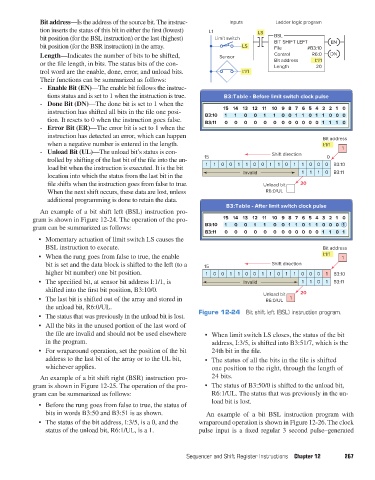
An example of a bit shift left (BSL) instruction pro-
gram is shown in Figure 12-24. The operation of the pro- 15 14 13 12 11 10 98 76 5 4 3 21 0
gram can be summarized as follows: B3:10 1 0 0 1 1 0 01 10 1 1 0 00 1
B3:11 0 0 0 0 0 0 00 00 0 0 1 10 1
• Momentary actuation of limit switch LS causes the
BSL instruction to execute. Bit address
• When the rung goes from false to true, the enable I:1/1 1
bit is set and the data block is shifted to the left (to a 15 Shift direction
higher bit number) one bit position. 1 0 0 1 1 00 1 1 0 1 1 0 00 1 B3:10
• The specified bit, at sensor bit address I:1/1, is Invalid 1 1 0 1 B3:11
shifted into the first bit position, B3:10/0. 20
• The last bit is shifted out of the array and stored in Unload bit 1
R6:0/UL
the unload bit, R6:0/UL.
• The status that was previously in the unload bit is lost. Figure 12-24 Bit shift left (BSL) instruction program.
• All the bits in the unused portion of the last word of
the file are invalid and should not be used elsewhere • When limit switch LS closes, the status of the bit
in the program. address, I:3/5, is shifted into B3:51/7, which is the
• For wraparound operation, set the position of the bit 24th bit in the file.
address to the last bit of the array or to the UL bit, • The status of all the bits in the file is shifted
whichever applies. one position to the right, through the length of
An example of a bit shift right (BSR) instruction pro- 24 bits.
gram is shown in Figure 12-25. The operation of the pro- • The status of B3:50/0 is shifted to the unload bit,
gram can be summarized as follows: R6:1/UL. The status that was previously in the un-
load bit is lost.
• Before the rung goes from false to true, the status of
bits in words B3:50 and B3:51 is as shown. An example of a bit BSL instruction program with
• The status of the bit address, I:3/5, is a 0, and the wraparound operation is shown in Figure 12-26. The clock
status of the unload bit, R6:1/UL, is a 1. pulse input is a fixed regular 3 second pulse–generated
Sequencer and Shift Register Instructions Chapter 12 267
pet73842_ch12_252-280.indd 267 03/11/15 7:20 PM