
Page 342 - Programmable Logic Controllers, Fifth Edition - Mobile version
P. 342
I/O Module DeviceNet
Scanner
Module
4-wire cable
Conventional system and connector DeviceNet system
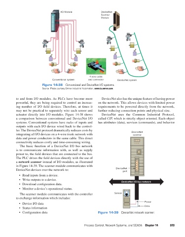
Figure 14-38 Conventional and DeviceNet I/O systems.
Source: Photo courtesy Omron Industrial Automation, www.ia.omron.com.
to and from I/O modules. As PLCs have become more DeviceNet also has the unique feature of having power
powerful, they are being required to control an increas- on the network. This allows devices with limited power
ing number of I/O field devices. Therefore, at times it requirements to be powered directly from the network,
may not be practical to separately wire each sensor and further reducing connection points and physical size.
actuator directly into I/O modules. Figure 14-38 shows DeviceNet uses the Common Industrial Protocol,
a comparison between conventional and DeviceNet I/O called CIP, which is strictly object oriented. Each object
systems. Conventional systems have racks of inputs and has attributes (data), services (commands), and behavior
outputs with each I/O device wired back to the control-
ler. The DeviceNet protocol dramatically reduces costs by
integrating all I/O devices on a 4-wire trunk network with DeviceNet
scanner
data and power conductors in the same cable. This direct
connectivity reduces costly and time-consuming wiring.
The basic function of a DeviceNet I/O bus network
is to communicate information with, as well as supply
power to, the field devices that are connected to the bus.
The PLC drives the field devices directly with the use of
a network scanner instead of I/O modules, as illustrated
in Figure 14-39. The scanner module communicates with
DeviceNet devices over the network to: DeviceNet
port
• Read inputs from a device.
• Write outputs to a device. DeviceNet I/O bus network
• Download configuration data.
• Monitor a device’s operational status.
The scanner module communicates with the controller Sensor
to exchange information which includes:
• Device I/O data Power
• Status information Data
• Configuration data Figure 14-39 DeviceNet network scanner.
Process Control, Network Systems, and SCADA Chapter 14 323
pet73842_ch14_305-332.indd 323 05/11/15 4:29 PM