
Page 116 - Servo Motors and Industrial Control Theory
P. 116
110 6 AC Servo Motors
P
+
TH1 D1 TH3 D3 TH5 D5
V j R S T
TH4 D4 TH6 D6 TH2 D2
-
N
i A i C i s i r
Z
ZZ
i A i B
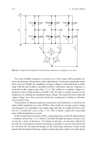
Fig. 6.8 A simple circuit diagram for the principle operation of a frequency converter
The most available frequency converters are of three types with acceptable dy-
namic performance for position control applications. In the pulse amplitude modu-
lated converter (PAM), the amplitude of output voltage is controlled at the rectifier
stage with the aid of phase controlled rectifiers (thyristors) and the frequency is
controlled at the output stage (Fig. 6.11a). This achieves a constant voltage–to–
frequency ratio at high frequency and the volts: Hz ratio is usually boosted at low
frequencies by limiting the minimum output voltage. The main drawback is that the
output voltage wave form generates harmonics components resulting in vibration
and excessive noise.
The problem of vibration and noise associated with PAM drive is solved in the
pulse-width modulated converter (PWM), where both the average output voltage
and frequency are controlled at the output stage after the AC supply has been recti-
fied to a constant DC source (Fig. 6.11b). This is further improved if sinusoidal
pulse width modulations are used.
In the Current Source Inverter (CSI), a large inductance in the DC link produces
a constant current (Fig. 6.11c), which is switched through the phases of motor coils
in turn by a series of thyristors. The diodes in all types of converters effectively
provide the commutations function and ensure continuity in current when thyristors
are switched off. The main advantage of CSI is that large inductance in the circuit
protects the electronics from any sudden current surge that could occur under faulty