
Page 196 - Servo Motors and Industrial Control Theory
P. 196
Appendix B 193
and A is a constant which depends on the flux density of the bearing, number
of wire turns, and the material properties of the core iron flux density. All these
parameters depend on the design configuration of the bearing which must be
considered at the design stage.
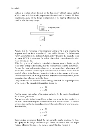
V
magnetic poles
x
shatt
V
Assume that the resistance of the magnetic wiring is 0.2 Ω and linearize the
magnetic nonlinear force around x = 0.2 mm and I = 50 amps. To find the con-
stant A assume that at the distance 0.2 mm and I = 20 amps, the magnetic force
is around 1000 N. Assume that the weight of the shaft refereed at the location
of the bearing is 5 kg.
Write the equation of motion in vertical direction and assume that the weight
of the shaft acting on the bearing may be considered as an input disturbance.
Convert the linearized equation of motion in state space form where there will
be two state variables and two inputs of the external disturbance force F and the
applied voltage to the bearing. Ignore the frictions in the system which repre-
sent the worst condition. If any parameters and variables are not defined, select
an engineering value or symbol for them.
Design state variable feedback control strategy in which the required position
of the roots of the characteristic equation should be,
s :=− 20
1
s :=− 30
2
Find the steady state values of the output variables for the required position of
the shaft as x = 0.2 mm.
i
Add an integrator in the forward loop so that zero error for step input of x is
i
achieved. Determine the gains of the state variable feedback which in this case
is three. Assume that the desired position of the roots of the characteristic equa-
tion should be,
s :=− 20
1
s :=− 30
2
s :=− 40
3
Design a state observer so that all the state variables can be predicted for feed-
back purpose. To design an observer you should measure at least one output
variable which in this case is the same as one of the state variable x.