
Page 198 - Servo Motors and Industrial Control Theory
P. 198
Appendix B 195
There is also a damper C which tries to limit the vibration of the wheel trans-
mitted to the car and prevents excessive vibrations transmitted to the car. The
value of k1 is limited by the weight of the car and dynamic force being trans-
mitted to it. K2 is the subject of further research as to limit the displacement
of the road bump being transmitted to the suspension. Assume the following
numerical values for the parameters involved in the equation of motions.
M1 300 kg=
M2 = 20 kg
K1 10000 N/m=
K2 1000 N/m=
For derivation of equation of motions assume that all masses displacement is
measured from the static equilibrium conditions and so you can ignore the weight
of the mass in equations of motion. Consider the damper constant as it is required
to determine its value to limit the vibration of the car. Write the equation of mo-
tions for both masses and convert them to state space form. First assume that C = 0
and find the eigenvalues of the state matrix. In this case there is no damping in
the system and all eigenvalues have 0 real part. Then change C gradually and find
the corresponding eigenvalues. Repeat this process until a satisfactory damping
ratio appears in a pair of eigenvalues that correspond to the vibration of the car.
You should know that the input to the system is u, the displacement of the tire.
Assume a harmonic excitation and determine the frequency spectrum of the
two displacements of X1 and X2. Discuss the two frequency responses and
discuss what conclusions you can make from the frequency responses. Repeat
this process for several values of the damper coefficients C.
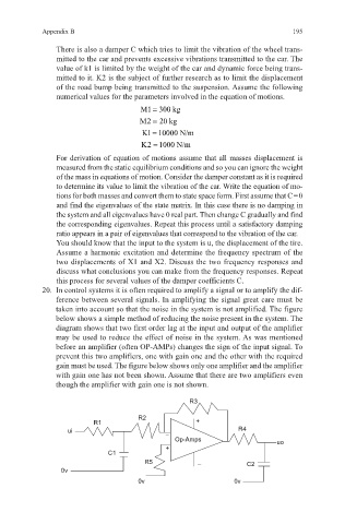
20. In control systems it is often required to amplify a signal or to amplify the dif-
ference between several signals. In amplifying the signal great care must be
taken into account so that the noise in the system is not amplified. The figure
below shows a simple method of reducing the noise present in the system. The
diagram shows that two first order lag at the input and output of the amplifier
may be used to reduce the effect of noise in the system. As was mentioned
before an amplifier (often OP-AMPs) changes the sign of the input signal. To
prevent this two amplifiers, one with gain one and the other with the required
gain must be used. The figure below shows only one amplifier and the amplifier
with gain one has not been shown. Assume that there are two amplifiers even
though the amplifier with gain one is not shown.
R3
R2
R1 +
ui R4
–
Op-Amps uo
+
C1
R5 – C2
0v
0v 0v