
Page 20 - Servo Motors and Industrial Control Theory
P. 20
12 1 Feedback Control Theory
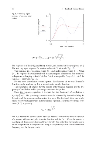
Fig. 1.7 Unit step input 2
response of a second order 2.0
system
response for unit input g(t) 1
f(t)
0.0 0
0 5 10
0.0 t 10
wnt, Time for wn=1
π 1 ξ− 2
φ
(θ = + )……… = tan ( )
φ
−
1
2 ξ
The response is a decaying oscillatory motion, and the rate of decay depends on ξ.
The unit step input response for various values of ξ is shown in Fig. 1.7.
The response is overdamped when ξ > 1 and underdamped when ξ < 1. When
ξ = 1, the response is overdamped with maximum speed of response. For most con-
trol systems, a damping ratio of ξ = 0.7 or ξ = 0.8 is acceptable. For ς = 0.1, ς = 0.5 the
response is shown in Fig. 1.7.
For the most complicated control system, the elements of its overall transfer
function can be modeled by first or second order transfer function.
The parameters of interest for the second order transfer function are the fre-
quency of oscillation and its percentage overshoot for ς < 1.0.
From the response equation, it is clear that the frequency of oscillation is
ω d =ω n 1 ς− 2 . The percentage overshoot can be obtained by first calculating the
derivative of the response and equating it to zero. The first peak then can be ob-
tained by substituting for time in the response equation. Then the percentage over-
shoot ( P.O) is given by
( ξπ− .)
. : 100.e=
PO 1 ξ− 2
The two parameters defined above can also be used to obtain the transfer function
of a system with second order transfer function and for ξ < 1. When the system is
overdamped, it is possible to model the system by first order transfer function or to
obtain two points on the response and using the response equation to find the natural
frequency and the damping ratio.