
Page 205 - Servo Motors and Industrial Control Theory
P. 205
202 Appendix B
at least 0.5. The exact values of the real and imaginary parts should be chosen
so that the system is not too fast so that the force F can be adjusted as required.
You choose some arbitrary values for the eigenvalues.
30. This is a repeat of problem 18 with different numerical values for the param-
eters of the system. Compare the result of this problem with problem 18 and
discuss the differences. An interesting problem is how to control the position
of a ball on a beam. The beam can be rotated about its center of gravity by a
torque which can be generated by a motor. At first attempt of the problem it is
assumed that the torque can be generated without any time delay compared to
the time delay involved in the system. The position of the ball can be measured
using different techniques. One method is to attach a linear potentiometer on
the beam and as the ball moves on the beam it gives a signal proportional to
the displacement of the ball. For state variable feedback control strategy, the
ball’s velocity must also be measured. This can be achieved by differentiating
the position signal. It is assumed that the position sensor is so accurate that the
noise on the signal is negligible. In addition the rotating angle and the rotating
velocity of the beam must also be measured. It is assumed that these signals
are also available for implementing the state variable feedback control strategy.
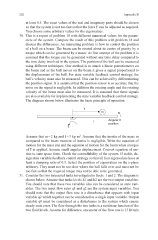
The diagram shown below illustrates the basic principle of operation.
y
m
I Angular θ
position
T
Assume that m = 2 kg and I = 3 kg·m . Assume that the inertia of the mass m
2
compared to the beam moment of inertia is negligible. Write the equation of
motion for the mass (m) and the equation of motion for the beam when a torque
of T is applied. Assume small angular displacement. Convert equation of mo-
tion to state space form. Check the controllability of the system. If stable, de-
sign state variable feedback control strategy so that all four eigenvalues have at
least a damping ratio of 0.5. Select the position of eigenvalues on the s-plane
arbitrary. They must not be too slow where the ball falls over and must not be
too fast so that the required torque may not be able to be generated.
31. Consider the two interacted tanks investigated in Sects. 1 and 2. The diagram is
shown below. Assume that tanks levels h1 and h2 are the two output variables.
You should note that these two variables also can be considered as state vari-
ables. The two input flow rates q1 and q2 are the system input variables. You
should note that the output flow rate is a disturbance that appears with input
variable q2 which together can be considered as a single input variable. Output
variable q0 must be considered as a disturbance to the system which causes
steady state error. The flow through the two tanks is a nonlinear function of the
two fluid levels. Assume for difference, one meter of the flow rate is 15 lit/min