
Page 92 - Servo Motors and Industrial Control Theory
P. 92
4.8 Effect of Form Factor on Speed Fluctuation 85
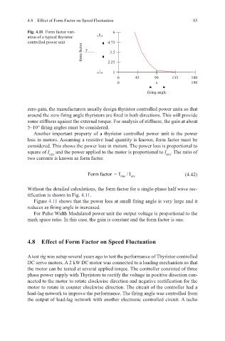
Fig. 4.11 Form factor vari- 6
ation of a typical thyristor 6
controlled power unit 4.75
form factor y 2.25
3.5
1 1
0 45 90 135 180
0 x 180
firing angle
zero gain, the manufacturers usually design thyristor controlled power units so that
around the zero firing angle thyristors are fired in both directions. This will provide
some stiffness against the external torque. For analysis of stiffness, the gain at about
5–10° firing angles must be considered.
Another important property of a thyristor controlled power unit is the power
loss in motors. Assuming a resistive load quantity is known, form factor must be
considered. This shows the power loss in motors. The power loss is proportional to
square of I and the power applied to the motor is proportional to I . The ratio of
rms
ave
two currents is known as form factor.
Form factor =I I / (4.42)
rms ave
Without the detailed calculations, the form factor for a single-phase half wave rec-
tification is shown in Fig. 4.11.
Figure 4.11 shows that the power loss at small firing angle is very large and it
reduces as firing angle is increased.
For Pulse Width Modulated power unit the output voltage is proportional to the
mark space ratio. In this case, the gain is constant and the form factor is one.
4.8 Effect of Form Factor on Speed Fluctuation
A test rig was setup several years ago to test the performance of Thyristor controlled
DC servo motors. A 2 kW DC motor was connected to a loading mechanism so that
the motor can be tested at several applied torque. The controller consisted of three
phase power supply with Thyristors to rectify the voltage in positive direction con-
nected to the motor to rotate clockwise direction and negative rectification for the
motor to rotate in counter clockwise direction. The circuit of the controller had a
lead-lag network to improve the performance. The firing angle was controlled from
the output of lead-lag network with another electronic controlled circuit. A tacho