
Page 853 - Mechatronics with Experiments
P. 853
®
®
MATLAB , SIMULINK , STATEFLOW, AND AUTO-CODE GENERATION 839
menu selection. This creates a model window with name “Untitled.” Now we can pick
®
different blocks from the Simulink Library Browser window, drag them into the “Untitled”
model window and build a model. Help can be obtained on any library block by right-
clicking on it, and selecting “Help” from the “context-sensitive menu.” Basic properties of
a block, such as orientation of the block and so on, can be accessed through the block’s
context-sensitive properties menu. Each block has a name which is by default placed under
the block. The names are strictly for the benefit of the user and are not used as a variable
®
reference in the Simulink operations. The names of the blocks must be unique, in other
words, the same name cannot be used for more than one block. The parameters of a block
are accessed by double-clicking on it. The model is saved in the “Untitled” model window
menu:
File → Save As: enter filename (extension is “.mdl”).
Once a name is specified for the model and saved, the window title for the model window
changes from “Untitled” to the specified file name.
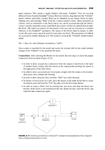
Connections: After selecting the blocks for the model, the next step is to draw the proper
connections between them (Figure A.11).
In order to draw straight line connections from the output of one block to the input
of another block, simply click the mouse at the output point and drag the mouse to
the input point of the other block.
In order to draw a perpendicular break point, simply click the mouse in the interme-
diate point, then continue the drawing.
In order to draw diagonal lines, hold the “Shift” key while drawing.
To define a branch point on a line, place the mouse at the point on the line to create
the branch point and hold the “Ctrl” key plus click the left mouse button.
In order to insert a block over an existing line, just move and drop the block over
the line. If the block is not inserted into the line, delete the line, insert the block, and
make the line connections again.
1
s
Integrator 1
1
+
– s
Soope
Signal Integrator
generator
®
FIGURE A.11: Drawing connections in Simulink : straight and perpendicular lines, diagonal
lines, creating break points on a line.