Page 62 - FLEXTRAY Cable Management - Complete Catalog
P. 62
Flextray™ - Installation
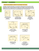
Recommended Support Locations For Fabricated Tray Fittings
The following are recommended support diagrams to serve as guidelines for installing wire basket cable support systems in the field.
The information is intended to provide the installer some practical assistance when estimating the amounts of supports and to help in
identifying support locations for various field conditions for the installer. It does not, however, cover every situation that may arise when
Installation trays with long radii, or those with multiple side wires cut may require additional support to avoid unwanted deflection.
installing the product. It may be possible to install narrow trays with lighter loads and fewer supports. Wider trays with heavier loading,
2'-0'
(610mm)
2'-0'
(610mm) Splice
Joint
2'-0'
2'-0' (610mm)
(610mm) W
2'-0'
(610mm)
Horizontal Elbow Support Horizontal Tee Support Horizontal Wye Support
Inside corner supports are not On 24" wide items, one support On 24" wide items,
required on 90° may be placed at the mid-point recommended distance is
short radius bends. of the back span as illustrated. 1 ft. 6 in. (457mm) from splice
connection.
2'-0' 2'-0'
(610mm) (610mm)
2'-0'
2'-0'
(610mm)
(610mm) Splice
Joint
Horizontal Cross Support Straight Reducer Support
On 24" wide items, recommended Place reducer supports within
distance is 1 ft. 6 in. (457mm) from 2 ft. (610mm)
splice connection. of each splice connection.
2'-0' 2'-0'
(610mm) (610mm)
Bend Distance
Top
Support
Splice
Joint
Left/Right Reducer Support Vertical Elbows
Place reducer supports within Support vertical elbows at top
2 ft. (610mm) support location.
of each splice connection. Bend distances of 4 ft. (1219mm)
and over should be supported at
each end as illustrated.
60