
Page 135 - Icon Ridge Presents ORION
P. 135
Thread tools \ Technical introduction – thread milling
Selecting the thread milling cutter diameter
Process:
In contrast to tapping, where sections are cut out of the material, thread forming is a non-cutting, pressure forming procedure.
Advantages:
No chip formation
Up to 30% higher surface quality than with thread cutting
Up to 40% higher processing speed than with thread cutting
Threads in through holes and blind holes can be produced with the same tool
Wide range of materials processable
Cutting of thread eliminated
Thread pitch and thread angle errors as with cut threads eliminated
Shaped threads have higher strength owing to non-continuous cut
Requirements: For all shapeable materials with elongation >10 %.
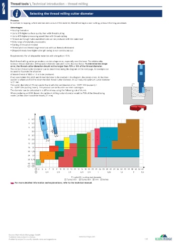
Each thread milling cutter generates a certain shape error, especially near the base. The relationship
between thread diameter, milling cutter diameter and pitch is the decisive factor. To minimise the shape
error, the thread cutter diameter should not be larger than 70% ± 15% of the thread diameter.
The correct thread cutter diameter can be determined using the diagram on the next page. An example can
be used to illustrate the situation:
A female thread of M30 x 1.5 is to be produced.
If we now include the pitch and thread diameter to be created in the diagram, the points cross. At the inter-
section is where we find the recommended thread cutter diameter. In our case, the optimum cutter diameter
is 21 mm.
The cutter diameter of 21 mm can be found with the combination of no. 13397 035 (support) + d=30
no. 13397 226 (cutting insert). This product can be found in our main catalogue.
The diameter can be calculated in a different way using the following rule of thumb. P=1,5
When producing an M30 thread, the optimum milling cutter diameter would be 70% of the thread being
made. (In this case it would be exactly 21 mm)
4 6,0
5 5,0
6 4,0
3,5 P
8 3,0 D D=21 D=29
10 2,5 D 10 D=14 D=17 D=18
12 2,0 7 8
16 1,5
5
20 1,25
6
24 1,0 4 D=9 D=12
32 0,75
3
48 0,5
1 2
3 3 5 6 7 8 9 10 11 12 13 14 15 16 18 20 22 24 26 28 30 32 34 36 38 40 44 48 52 56 64
4 1/4 3/8 1/2 5/8 3/4 1 1,25 1,5 2 2,5
P = pitch D = cutting tool diameter
① Turns/inch ② Turns/mm ③ mm ④ inches
h For more detailed information and explanations, refer to the technical manual.
Source: Hahn+Kolb Werkzeuge GmbH
Technical data subject to change. www.iconridge.com
Availability subject to country specific rules and regulations. 135
0272_EN_2018_KERN[21847304]-i.indd 272 12/17/2018 3:32:04 PM