
Page 245 - Icon Ridge Presents ORION
P. 245
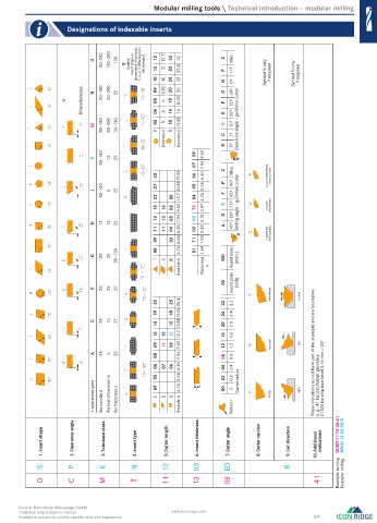
Modular milling tools \ Technical introduction – modular milling
Designations of indexable inserts
U 80–250 130–380 130 X Scalene insert shape or dimensions of symbols 5, 6, or 7 differing from the standard 12 12 10 12.7 12 10 32 25 25 32 25.4 25 Z Z P P Misc. 11º 11° Symbol N only if required Symbol N only if required
O Miscellaneous N 50–150 80–200 25 09 08 06 9,52 8 6 20 19 16 20 19.05 16 N N G G F F 0º 0° 30º 30° 25º 25°
M 50–150 80–200 50–130 05 R R 5 15 R R 15.88 E E D D 20º 20° 15º 15° Clearance angle – guillotine cutter
Incircle d Incircle d C C B B 7° 7º 5º 5°
50–150 13 25 07 7.94
K 09 9.52
33 15.88 19.05 06 6.35 Z Z P P Misc. . double-chamfered and rounded
J 50–150 5 25 27 22 08 12.7 05 04 5.56 4.76 F F 90º 90° 85° 85º
16 16 06 9.52 T3 3.97 E E 75° 75º Setting angle – guillotine cutter double- chamfered
13 13 05 7.94 03 3.18 D D 60° 60º
H 13 13 25 A A 45º 45°
11 11 04 6.35 02 2.38 chamfered and rounded
09 03 5.56 T1 1.98
G 25 25 50–130 08 T T V V W W 4.76 01 1.59 MO MO Round plate (metr.)
Incircle d Thickness s
00 00 Round plate (inch)
E 25 25 25 chamfered
25 25 25.4 32 32 3.2 3.2 neutral
19 19 24 24 2.4 2.4
C 25 13 25 16 15 15.88 19.05 20 20 2.0 2.0
12 15 12 12.7 16 16 1.6 1.6
09 11 09 9.52 12 12 1.2 1.2 rounded left
A 25 5 25 08 7.94 08 08 0.8 0.8 These indications do not form part of the standard and are facultative.
06 05 07 06 6.35 5.56 04 04 02 02 0.4 0.4 0.2 0.2 01520 for chip face bezel 0.15 mm 20º
± tolerances (m) for incircle d for test dimension m for thickness s 04 C C D D S S 4.76 Incircle d 00 00 Radius r 0 0 Corner radius sharp right e. g.–41 for chip former geometry
1. Insert shape 2. Clearance angle 3. Tolerance class 4. Insert type 5. Cutter length 6. Insert thickness 7. Cutter angle 8. Cutter version 9. Cut direction 10. Additional indications DCMT 11 T3 08-41 SPKN 12 03 ED R
S S P P K K N N 12 12 03 ED R Example: turning Example: milling
D D C C M M T T 11 11 T3 08 -41
Source: Hahn+Kolb Werkzeuge GmbH
Technical data subject to change. www.iconridge.com
Availability subject to country specific rules and regulations. 245
0474_EN_2018_KERN[21847495]-i.indd 475 12/17/2018 3:32:52 PM