
Page 108 - From GMS to LTE
P. 108
94 From GSM to LTE-Advanced Pro and 5G
2.6 GPRS Radio Resource Management
As described earlier, a GPRS timeslot can be assigned to several users at the same time.
It is also possible to assign several timeslots to a single subscriber to increase their data
transmission speed. In any case, the smallest transmission unit that can be assigned to
a user is one block, which consists of four bursts on one timeslot on the air interface for
GPRS and two bursts for EDGE MCS 7–9. A block is also called a GPRS radio link
control/Medium Access Control (RLC/MAC) frame.
Temporary Block Flows (TBF) in the Uplink Direction
Every RLC/MAC frame on the PDTCH or PACCH consists of an RLC/MAC
header and a user data field. When a user wants to send data on the uplink, the
mobile device has to request for resources from the network by sending a Packet
Channel Request message via the RACH or the PRACH as previously shown in
Figure 2.12.
The PCU then answers with an Immediate Packet Assignment message on the AGCH.
The message contains information as to the timeslots in which the mobile device is
allowed to send data. As a timeslot in GPRS may not be used exclusively by a single
subscriber, a mechanism is necessary to indicate to a mobile device when it is allowed to
send on the timeslot. Therefore, the uplink assignment message contains a parameter
called the uplink state flag (USF). A different USF value is assigned to every subscriber
that is allowed to send on the timeslot. The USF is linked to the so‐called temporary flow
identity (TFI) of a temporary block flow (TBF). A TBF identifies data to or from a user
for the time of the data transfer. Once the data transfer is completed, the TFI is reused for
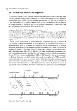
another subscriber. To know when it can use the uplink timeslots, the mobile device has
to listen to all the timeslots it has been assigned in the downlink direction. Every block
that is sent in the downlink to a subscriber contains a USF in its header as shown in
Figure 2.19. It indicates who is allowed to send in the next uplink block. By including the
USF (3 Bit)
RLC/MAC header User data
5 4 5 5
PDTCH downlink
Other
USF = 5 terminal
Assignment of
TFI (up) = 2
uplink permission
2 2 2
PDTCH uplink
TFI
Figure 2.19 Use of the uplink state flag.