
Page 278 - From GMS to LTE
P. 278
264 From GSM to LTE-Advanced Pro and 5G
Mobile source target
Device eNodeB eNodeB MME S-GW PDN-GW
S1
Measurement Report
Handover Request
Handover Request
Handover Req. Ack.
Create Indirect
Forward Tunnel Req.
Create Indirect
Handover Command
RRC Con. Reconfig. Forw. Tun. Req. Ack.
eNodeB Status Transfer
Random Access eNodeB Status Tr.
(Dedicated resources)
Uplink user data
Downlink user data
Forwarding
Forwarding
Handover Notify
Mod. Bearer Req.
UE Context Release
Mod. Bearer Resp.
UE Context Release Ack.
Del Indir. Tun.
Del Indir. Tun. Rsp.
Up/downlink data
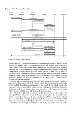
Figure 4.21 Basic S1‐based handover.
possible over the X2 interface between the source and target eNode‐Bs, it might still be
possible that the user data can be forwarded directly. This is called direct forwarding.
This is not the case in the scenario shown in Figure 4.21 and hence the MME requests
a Serving‐GW to create a temporary indirect tunnel between the source and the target
eNode‐B with a Create Indirect Forward Tunnel Request message. The Serving‐GW
that supports the indirect tunnel does not have to be the same gateway that is responsi-
ble for the default tunnel of the user. In this example, however, this is the case to reduce
complexity, and the Serving‐GW responds with a Create Indirect Forward Tunnel
Request Acknowledge message.
Once the indirect tunnel is created, the MME confirms the handover with a handover
command to the source eNode‐B. The source eNode‐B then executes the handover by
issuing an RRC Reconfiguration Command to the mobile device, which includes the
parameters of the target eNode‐B. It then stops forwarding downlink data to the mobile
device and sends its current user‐plane state, such as the packet counter, to the target
eNode‐B via the MME in an eNode‐B Status Transfer message.
User data packets still received in the uplink direction are forwarded directly to the
Serving‐GW. User data in the downlink direction arriving from the current Serving‐
GW are sent back to the core network to the Serving‐GW that supports the indirect
forward tunnel. This Serving‐GW then forwards the user data packets to the target
eNode‐B, where they are buffered until the radio connection to the mobile device has
been restored. Redirecting the downlink user data in this way creates additional traffic