
Page 283 - From GMS to LTE
P. 283
Long Term Evolution (LTE) and LTE-Advanced Pro 269
be found the network can also configure UMTS frequency bands and lists of GSM
channels as measurement objects.
Part 2 – Report Configurations: A report configuration can be a periodic report or
an event (A1–A5, B1, B2, etc.), i.e. a single report that is sent when the condition
described in the report configuration is met. Events can be further configured to trigger
periodic reporting once the condition has been met. This is useful, for example, if the
network wants to configure additional measurements when signal conditions further
deteriorate.
Part 3 – Measurements: In this part, measurement objects and report configurations are
assigned to each other. This allows assignment of some of the report configurations to one
of the measurement objects and other configurations to another measurement object.
Discontinuous Reception (DRX) in the Connected State to Save Power
Continuously scanning for scheduling grants in each subframe once a millisecond is
power consuming and should be avoided if the overall throughput required by a device
at one time is far below that which could be transferred if the device was scheduled in
every subframe. In LTE, it is possible to configure a device to only periodically check for
scheduling assignments. This functionality is referred to as DRX and works as follows.
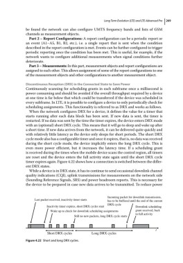
When the network configures DRX for a device, it defines the value for a timer that
starts running after each data block has been sent. If new data is sent, the timer is
restarted. If no data was sent by the time the timer expires, the device enters DRX mode
with an (optional) short DRX cycle. This means that it will go to sleep and wake up after
a short time. If new data arrives from the network, it can be delivered quite quickly and
with relatively little latency as the device only sleeps for short periods. The short DRX
cycle mode also has a configurable timer and once it expires, that is, no data was received
during the short cycle mode, the device implicitly enters the long DRX cycle. This is
even more power efficient, but it increases the latency time. If a scheduling grant
is received during the times when the mobile device scans the control region, all timers
are reset and the device enters the full activity state again until the short DRX cycle
timer expires again. Figure 4.22 shows how a connection is switched between the differ-
ent DRX states.
While a device is in DRX state, it has to continue to send occasional downlink channel
quality indications (CQI), uplink transmissions for measurements on the network side
(Sounding Reference Signals, SRS) and power headroom reports. This is necessary for
the device to be prepared in case new data arrives to be transmitted. To reduce power
Incoming packet for downlink transmission,
Last packet received, inactivity timer starts has to be buffered until the end of the current
DRX cycle
Inactivity timer expires, short DRX cycles start Downlink scheduling
Wake up to check for downlink scheduling assignments grant received, back
to full activity
Still no new packets, long DRX cycle starts
t
Short DRX cycles Long DRX cycles
Figure 4.22 Short and long DRX cycles.