
Page 294 - From GMS to LTE
P. 294
280 From GSM to LTE-Advanced Pro and 5G
the CDMA network until the handover has been executed. When the S103 user data
tunnel is in place, the handover is executed and the mobile device moves to the CDMA
network. Once there, the CDMA network informs the MME that the mobile device has
performed the handover successfully. The user data tunnel between the PDN‐GW and
the S‐GW is then redirected to the CDMA access network. In addition, the temporary
data forwarding tunnel over the S103 interface and user’s context in the eNode‐B are
removed.
4.11 Carrier Aggregation
When LTE was launched, a carrier bandwidth of up 20 MHz was revolutionary as it was
four times larger than the 5 MHz carriers used for UMTS, which was still considered
ample at the time. Over the years, however, bandwidth demands per cell site continued to
increase. 3GPP thus specified a way to combine several carriers into a transmission chan-
nel. This is referred to as Carrier Aggregation (CA). To remain backward compatible with
3GPP Release 8, the maximum carrier bandwidth of 20 MHz is not altered. Instead, car-
rier aggregation combines the capacity of several individual carriers. A typical configura-
tion used in practice in Europe at the time of publication combines one or more carriers
in LTE band 7 (2600 MHz band) and one or more carriers in band 3 (1800 MHz band) to
achieve a total carrier bandwidth of 40 to 60 MHz or even more in the downlink direction.
In addition, 800 MHz spectrum (band 20), the re‐farmed 900 and 2100 MHz spectrum
used by GSM and UMTS (bands 8 and 1 respectively), and newly available spectrum in
the 700 MHz and 1500 MHz frequency ranges are also candidates for carrier aggregation.
Carriers are usually aggregated asymmetrically as there is typically a higher demand
for bandwidth in the downlink than in the uplink. In the downlink direction, for exam-
ple, carriers in two or more bands are aggregated to a combined 40 to 60 MHz channel
at the time of publication, while in the uplink direction only a 20 MHz carrier in a single
band is used. Whether and how many carriers can be aggregated depends on how many
carriers are used at a base station site and the hardware capabilities of a mobile device,
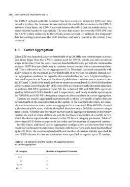
which the device signals to the network in the UE device category parameter. Table 4.7
shows typical UE device categories in use today and the number of supported carriers.
For the future, additional carrier aggregation configurations are foreseen that would
result in even broader transmission channels with five carriers and a total bandwidth of
up to 100 MHz, the maximum bandwidth and number of carriers initially specified. In
later 3GPP releases, further enhancements were specified to support up to 32 carriers.
Table 4.7 UE categories and the number of supported carriers
for carrier aggregation.
UE category Number of supported CA carriers
3, 4 1
6 2
9, 10 3
11, 12 4