
Page 299 - From GMS to LTE
P. 299
Long Term Evolution (LTE) and LTE-Advanced Pro 285
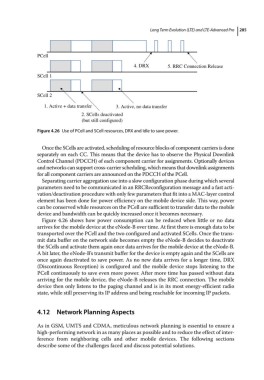
PCell
4. DRX 5. RRC Connection Release
SCell 1
SCell 2
1. Active + data transfer 3. Active, no data transfer
2. SCells deactivated
(but still configured)
Figure 4.26 Use of PCell and SCell resources, DRX and Idle to save power.
Once the SCells are activated, scheduling of resource blocks of component carriers is done
separately on each CC. This means that the device has to observe the Physical Downlink
Control Channel (PDCCH) of each component carrier for assignments. Optionally devices
and networks can support cross‐carrier scheduling, which means that downlink assignments
for all component carriers are announced on the PDCCH of the PCell.
Separating carrier aggregation use into a slow configuration phase during which several
parameters need to be communicated in an RRCReconfiguration message and a fast acti-
vation/deactivation procedure with only few parameters that fit into a MAC‐layer control
element has been done for power efficiency on the mobile device side. This way, power
can be conserved while resources on the PCell are sufficient to transfer data to the mobile
device and bandwidth can be quickly increased once it becomes necessary.
Figure 4.26 shows how power consumption can be reduced when little or no data
arrives for the mobile device at the eNode‐B over time. At first there is enough data to be
transported over the PCell and the two configured and activated SCells. Once the trans-
mit data buffer on the network side becomes empty the eNode‐B decides to deactivate
the SCells and activate them again once data arrives for the mobile device at the eNode‐B.
A bit later, the eNode‐B’s transmit buffer for the device is empty again and the SCells are
once again deactivated to save power. As no new data arrives for a longer time, DRX
(Discontinuous Reception) is configured and the mobile device stops listening to the
PCell continuously to save even more power. After more time has passed without data
arriving for the mobile device, the eNode‐B releases the RRC connection. The mobile
device then only listens to the paging channel and is in its most energy‐efficient radio
state, while still preserving its IP address and being reachable for incoming IP packets.
4.12 Network Planning Aspects
As in GSM, UMTS and CDMA, meticulous network planning is essential to ensure a
high‐performing network in as many places as possible and to reduce the effect of inter-
ference from neighboring cells and other mobile devices. The following sections
describe some of the challenges faced and discuss potential solutions.