
Page 329 - From GMS to LTE
P. 329
Long Term Evolution (LTE) and LTE-Advanced Pro 315
frequency
1 frame (10 ms) = 10 sub-frames (1 ms) = 20 slots (0.5 ms) next frame
180 kHz
1 sub-frame t
=
1 symbol = 1 resource block =
1 resource element 1 slot (0.5 ms) =
(15 kHz) 12 sub-carriers * 7 symbols
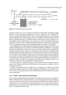
Figure 4.32 The NB‐IoT channel resource grid.
number of subcarriers as in a standard LTE Resource Block (RB). Scheduling mobile
devices to receive downlink transmissions, however, is different from standard LTE
with its very large channel bandwidths. Here, several mobile devices can receive data in
the downlink direction simultaneously as there are 50 RBs in a 10 MHz channel and 100
RBs in a 20 MHz channel. In a 180 kHz NB‐IoT channel, there is only 1 RB and it was
decided that only one mobile device can receive data at a time in the downlink direction
using all 12 subcarriers per 1‐millisecond subframe. Figure 4.32 shows this arrangement
and it is interesting to compare this drawing with Figure 4.8 earlier in the chapter.
In the uplink direction, the standard LTE 15 kHz spacing with Single Carrier Frequency
Division Multiple Access (SC‐FDMA) and BPSK and QPSK modulation has also been
maintained. Optionally, 3.75 kHz tones can be used. This option has been specified for
scenarios in which a device is able to receive data from the network but is unable to make
itself heard due to its small antenna, low transmission power, distance, signal conditions,
etc. By using 3.75 kHz instead of 15 kHz per tone, the transmission power can be focused
on a narrower channel, which significantly improves the link budget and the likelihood
of being heard at the base station side. Very weak signal conditions are referred to as
‘extreme coverage’ and NB‐IoT is specified to still work in radio conditions that are over
20 dB worse than those that would still be usable with GSM.
For devices that are optimized for power rather than ‘extreme coverage’ scenarios,
power class 5 has been specified, which limits the maximum power output of a device
to 20 dBm (0.1 Watt).
Unlike in the downlink where a single device is assigned all 12 subcarriers for data
transmission, uplink transmissions can be assigned per mobile device to a single tone or
to 3, 6 or all 12 tones (subcarriers) of the 180 kHz channel. This is referred to as multi-
tone transmission.
4.19.7 NB‐IoT – Control Channels and Scheduling
Due to these modifications the traditional LTE signaling channels are not reusable for
NB‐IoT. While the basic ideas like random access and assigning transmission opportu-
nities remain the same, the format and location of the channels is new. Similar to an LTE
channel, seven tones on the time axis are grouped into a 0.5‐ms slot and two slots are
grouped into a 1‐ms subframe, the smallest entity that can be scheduled. Ten subframes
form a 10‐millisecond radio frame.