
Page 334 - From GMS to LTE
P. 334
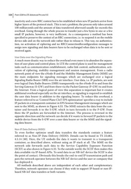
320  From GSM to LTE-Advanced Pro and 5G

            inactivity and a new RRC context has to be established when new IP packets arrive from
            higher layers of the protocol stack. This is not a problem; the process only takes around
            100 milliseconds and the amount of data transferred afterward usually far exceeds this
            overhead. Going through the whole process to transfer just a few bytes in one or a few
            small IP packets, however, is very inefficient. As a consequence a method has been
            specified to preserve the context of an RRC connection, i.e. to suspend it on the mobile
            device side and on the network side rather than to release it. This way, no authentica-
            tion, no activation of ciphering and no RRCConnectionReconfiguration messages to
            assign new signaling and data bearers have to be exchanged when data is to be sent or
            received again.

            User Data over the Signaling Plane
            A much more drastic way to reduce the overhead even more is to abandon the separa-
            tion of user plane and control plane. In LTE the control plane is used for management
            tasks such as communication establishment, radio link control, authentication, acti-
            vation of ciphering, mobility management and session management. From a radio
            network point of view the eNode‐B and the Mobility Management Entity (MME) are
            the main endpoints for signaling messages which are exchanged over a logical
            Signaling Radio Bearer (SRB) over the air interface. User data, i.e. IP packets, are sent
            over logical Data Radio Bearers (DRB) transparently via the eNode‐B to and from the
            Serving Gateway (S‐GW) and from there via the Packet Gateway (P‐GW) to and from
            the Internet. From a logical point of view this separation is important but it creates
            additional overhead especially on the air interface, as signaling is required to establish
            the user data bearer in addition to the signaling bearer. To reduce this overhead, a
            feature referred to as ‘Control Plane CIoT EPS optimization’ specifies a way to include
            IP packets in a transparent container in EPS Session Management messages which are
            sent to the MME, as shown in Figure 4.33. The MME extracts the data from the con-
            tainer and forwards it to the S‐GW, which in turn forwards it to the P‐GW. From
            there the IP packets are forwarded to the Internet. The process is reversed in the
            opposite direction and the network can decide if it wants to forward IP packets to the
            mobile device from the S‐GW over a user data bearer or via the MME and the signal-
            ing data bearer.

            Non‐IP Data Delivery (NIDD)
            To even further optimize small data transfers the standards contain a feature
            referred to as Non‐IP Data Delivery (NIDD). Details can be found in TS 23.682,
            4.5.14 [40]. Here, the UE embeds the data it wants to transmit in a transparent
            container, as described above, without using an IP stack at all. The MME on the
            network side forwards such data to the Service Capability Exposure Function
            (SCEF) as also shown in Figure 4.33. To the outside world, the SCEF then makes this
            data available via IP‐based APIs. To send data to an NB‐IoT device the SCEF is also
            the point of contact. Obviously this breaks the end‐to‐end IP transmission path and
            puts the network operator between the NB‐IoT device and the user or company that
            has deployed it.
             All methods described above are independent of each other and  complementary.
            Therefore, network operators can choose if they wish to support IP‐based or non‐IP‐
            based NB‐IoT data transfers or both variants.