
Page 375 - From GMS to LTE
P. 375
VoLTE, VoWifi and Mission Critical Communication 361
Function (ATCF) to prepare the ATGW for switching the voice data stream away from
one of the subscribers toward the IP address of the media gateway of the MSC‐Server.
This is done with a SIP Invite message. Once the ATCF has responded with a SIP ‘200
OK’ message and everything is prepared for a handover, the MSC‐Server then responds
with a ‘CS to PS Response’ message to the MME, which then triggers the handover by
sending a ‘Handover Command’ message to the mobile device.
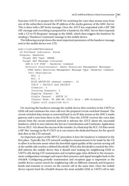
The following excerpt shows the most important parameters of the handover message
sent to the mobile device over LTE:
mobilityFromEUTRACommand
CS-Fallback Indicator: False
Purpose: Handover
Target RAT Type: GERAN
Target RAT Message Container
GSM A-I/F DTAP - Handover Command
Protocol Discriminator: Radio Resources Management Messages
DTAP Radio Resources Management Message Type: Handover Command
Cell Description
NCC: 2
BCC: 6
BCCH ARFCN(RF channel number): 32
TCH/F + FACCH/F and SACCH/F
Timeslot: 6
Training Sequence: 6
Hopping Channel: No
Single Channel : ARFCN 32
Channel Mode: FR AMR-WB (Full Rate - AMR-Wideband)
Cipher with algorithm A5/3
On receiving the handover message the mobile device then switches to the UMTS or
GSM cell and continues the voice call over the prepared circuit‐switched channel. The
circuit‐switched data stream is converted back to an IP data stream at the MSC’s media
gateway and is sent from there to the ATGW. Once the ATGW receives the voice data
stream from the circuit‐switched network it informs the ATCF about the successful
handover, which in turn informs the Service Centralization and Continuity Application
Server (SCC‐AS) about the success of the transfer. In a final step the SCC‐AS then sends
a SIP ‘Bye’ message to the P‐CSCF so it can remove the dedicated bearer for the speech
data flow in the LTE network.
An important aspect of the SRVCC procedure is how the handover is initiated in the
first place. Typically, the LTE network configures measurements to be made by the UE
to allow it to become aware when the downlink signal quality of the current serving cell
at the mobile side reaches a defined threshold. When this threshold is reached the eNo-
deB informs the mobile device that it should start looking for neighboring GSM or
UMTS cells during LTE transmission and reception gaps (also defined in the measure-
ment configuration message) and report their presence and signal strengths back to the
eNodeB. Configuring periodic transmission and reception gaps is important as the
mobile device cannot search for neighboring cells on different channels and frequency
bands and transmit or receive on the current cell at the same time. Once the mobile
device reports back the eNodeB chooses the most suitable GSM or UMTS cell to take