
Page 411 - From GMS to LTE
P. 411
Wireless Local Area Network (WLAN) 397
Wireless users
BSS
1 2
A B
Access point Ethernet
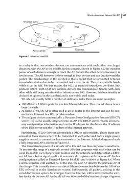
Figure 6.2 Infrastructure BSS.
as a relay is that two wireless devices can communicate with each other over larger
distances, with the AP in the middle. In this scenario, shown in Figure 6.2, the transmit
power of each device is enough to reach the AP but not the other device, because it is
too far away. The AP, however, is close enough to both devices and can thus forward the
packet. The disadvantage of this method is that a packet that is transmitted between
two wireless devices has to be transmitted twice over the air. Thus, the available band-
width is cut in half. For this reason, the 802.11e standard introduces the direct link
protocol (DLP). With DLP, two wireless devices can communicate directly with each
other while still being members of an infrastructure BSS. However, this functionality is
declared as optional in the standard and is not widely used today.
WLAN APs usually fulfill a number of additional tasks. Here are some examples:
100 Mbit/s or 1 Gbit/s ports for wireline Ethernet devices. Thus, the AP also acts as a
●
layer‐2 switch.
At home, a WLAN AP is often used as an IP router to the Internet and can be con-
●
nected via Ethernet to a DSL or cable modem.
To configure devices automatically, a Dynamic Host Configuration Protocol (DHCP)
●
server [10] is also usually integrated into an AP. The DHCP server returns all neces-
sary configuration information, such as the IP address for the device, the IP address
of the DNS server and the IP address of the Internet gateway.
Furthermore, WLAN APs can also include a DSL or cable modem. This is quite con-
venient as fewer devices have to be connected to each other and only a single power
supply is needed to connect the home network to the Internet. A block diagram of such
a fully integrated AP is shown in Figure 6.3.
The transmission power of a WLAN AP is low and can thus only cover a small area.
To increase the range of a network, several APs that cooperate with each other can be
used. If a mobile user changes their position and the network card detects that a differ-
ent AP has a better signal quality, it automatically registers with the new AP. Such a
configuration is called an Extended Service Set (ESS) and is shown in Figure 6.4. When
a device registers with another AP of the ESS, the new AP informs the previous AP of
the change. This is usually done via a direct Ethernet connection between the APs of an
ESS, referred to as the ‘distribution system’. Subsequently, all packets arriving in the
wired distribution system, for example, from the Internet, will be delivered to the wire-
less device via the new AP. As the old AP was informed of the location change, it ignores