
Page 56 - From GMS to LTE
P. 56
42 From GSM to LTE-Advanced Pro and 5G
unused, as the datarate required by the AMR‐WB codec is only 12.65 kbit/s. In practice,
AMR‐WB is mostly used in UMTS networks today. Therefore, it is described in more
detail in Chapter 3.
While the PCM algorithm digitizes analog volume levels by statically mapping them
to digital values, GSM speech digitization is much more complex in order to reach the
desired compression rate. In the case of the FR codec, which is specified in 3GPP TS
46.010 [25], the compression is achieved by emulating the human vocal system. This is
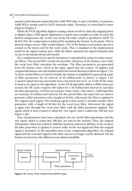
done by using a source–filter model (Figure 1.33). In the human vocal system, speech is
created in the larynx and by the vocal cords. This is emulated in the mathematical
model in the signal creation part, while the filters represent the signal formation that
occurs in the human throat and mouth.
On a mathematical level, speech formation is simulated by using two time‐invari-
ant filters. The period filter creates the periodic vibrations of the human voice while
the vocal tract filter simulates the envelope. The filter parameters are generated
from the human voice, which is the input signal into the system. To digitize and
compress the human voice, the model is used in the reverse direction as shown in Figure 1.33.
As time‐variant filters are hard to model, the system is simplified by generating a pair
of filter parameters for an interval of 20 milliseconds as shown in Figure 1.34.
A speech signal that has previously been converted into an 8‐ or 13‐bit PCM codec
is used as an input to the algorithm. As the PCM algorithm delivers 8000 values per
second, the FR codec requires 160 values for a 20‐millisecond interval to calculate
the filter parameters. As 8 bits are used per value, 8 bits × 160 values = 1280 input bits
are used per 20‐millisecond interval. For the period filter, the input bits are used to
generate a filter parameter with a length of 36 bits. Afterward, the filter is applied to
the original input signal. The resulting signal is then used to calculate another filter
parameter with a length of 36 bits for the vocal tract filter. Afterward, the signal
is again sent through the vocal tract filter with the filter parameter applied. The
signal which is thus created is called the ‘rest signal’ and is coded into 188 bits (see
Figure 1.34).
Once all parameters have been calculated, the two 36‐bit filter parameters and the
rest signal, which is coded into 188 bits, are sent to the receiver. Thus, the original
information, which was coded in 1280 bits, has been reduced to 260 bits. In the receiver,
the filter procedure is applied in reverse order on the rest signal and thus the original
signal is recreated. As the procedure uses a lossy compression algorithm, the original
signal and the recreated signal at the other end are no longer exactly identical. For the
human ear, however, the differences are almost inaudible.
Signal creation Signal forming
Vocal tract Voice
Source Period filter
filter
Filter parameters
Figure 1.33 Source–filter model of the GSM FR codec.