
Page 275 - Basic Electrical Engineering
P. 275
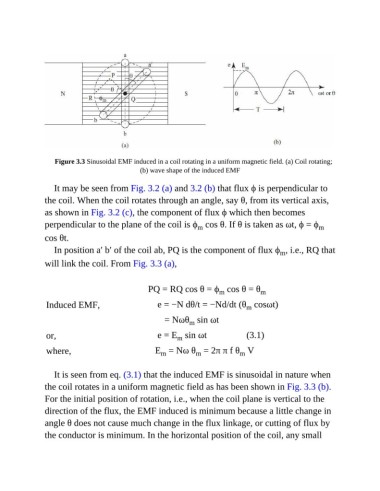
Figure 3.3 Sinusoidal EMF induced in a coil rotating in a uniform magnetic field. (a) Coil rotating;
                                              (b) wave shape of the induced EMF

                  It may be seen from Fig. 3.2 (a) and 3.2 (b) that flux ϕ is perpendicular to

               the coil. When the coil rotates through an angle, say θ, from its vertical axis,
               as shown in Fig. 3.2 (c), the component of flux ϕ which then becomes
               perpendicular to the plane of the coil is ϕ  cos θ. If θ is taken as ωt, ϕ = ϕ           m
                                                                 m
               cos θt.

                  In position a′ b′ of the coil ab, PQ is the component of flux ϕ , i.e., RQ that
                                                                                           m
               will link the coil. From Fig. 3.3 (a),


                                                 PQ = RQ cos θ = ϕ  cos θ = θ        m
                                                                        m
                Induced EMF,                         e = −N dθ/t = −Nd/dt (θ  cosωt)
                                                                                m
                                                        = Nωθ  sin ωt
                                                              m
                or,                                  e = E  sin ωt                 (3.1)
                                                          m
                where,                              E  = Nω θ  = 2π π f θ  V
                                                                m
                                                                              m
                                                     m
                  It is seen from eq. (3.1) that the induced EMF is sinusoidal in nature when
               the coil rotates in a uniform magnetic field as has been shown in Fig. 3.3 (b).

               For the initial position of rotation, i.e., when the coil plane is vertical to the
               direction of the flux, the EMF induced is minimum because a little change in

               angle θ does not cause much change in the flux linkage, or cutting of flux by
               the conductor is minimum. In the horizontal position of the coil, any small