
Page 428 - Basic Electrical Engineering
P. 428
only one coil per phase has been shown. In practice a number of coils
connected in series makes one phase winding.
When the magnetic poles are rotated by a prime mover (say a turbine), the
magnetic flux of North and South poles will cut the windings in sequence.
For clockwise rotation, flux will be cut by coil RR′ first, then by coil YY′,
and then by coil BB′. Therefore, EMF will be induced in these coils in
sequence. There will be a time phase difference between the EMFs induced
in these coils (windings). The time phase difference will be 120°. In terms of
time, the phase difference will be the time taken by the magnetic poles to
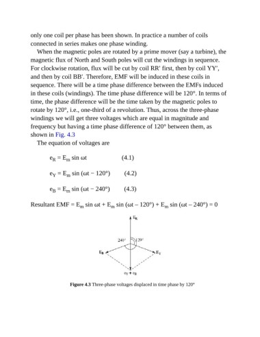
rotate by 120°, i.e., one-third of a revolution. Thus, across the three-phase
windings we will get three voltages which are equal in magnitude and
frequency but having a time phase difference of 120° between them, as
shown in Fig. 4.3
The equation of voltages are
e = E sin ωt (4.1)
R
m
e = E sin (ωt − 120°) (4.2)
m
Y
e = E sin (ωt − 240°) (4.3)
m
B
Resultant EMF = E sin ωt + E sin (ωt – 120°) + E sin (ωt – 240°) = 0
m
m
m
Figure 4.3 Three-phase voltages displaced in time phase by 120°