
Page 435 - Basic Electrical Engineering
P. 435
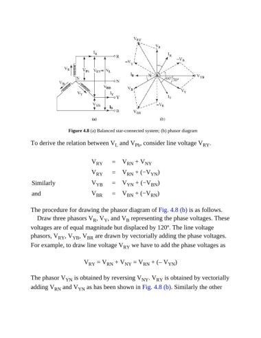
Figure 4.8 (a) Balanced star-connected system; (b) phasor diagram

               To derive the relation between V  and V , consider line voltage V                RY .
                                                       L
                                                                Ph


                                            V RY     =    V RN   + V NY

                                            V RY     =    V RN   + (−V  YN )

                Similarly                   V YB     =    V YN   + (−V  BN )

                and                         V BR     =    V BN   + (−V  RN )


               The procedure for drawing the phasor diagram of Fig. 4.8 (b) is as follows.
                  Draw three phasors V , V , and V  representing the phase voltages. These
                                                  Y
                                             R
                                                            B
               voltages are of equal magnitude but displaced by 120º. The line voltage
               phasors, V   RY , V YB , V  are drawn by vectorially adding the phase voltages.
                                          BR
               For example, to draw line voltage V         RY  we have to add the phase voltages as


                                        V  RY  = V RN  + V NY   = V RN  + (– V  YN )


               The phasor V     YN  is obtained by reversing V     NY  . V RY  is obtained by vectorially
               adding V   RN   and V  YN  as has been shown in Fig. 4.8 (b). Similarly the other