
Page 471 - Basic Electrical Engineering
P. 471
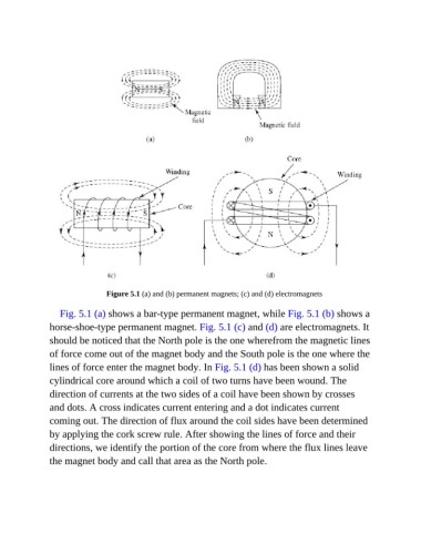
Figure 5.1 (a) and (b) permanent magnets; (c) and (d) electromagnets

                  Fig. 5.1 (a) shows a bar-type permanent magnet, while Fig. 5.1 (b) shows a

               horse-shoe-type permanent magnet. Fig. 5.1 (c) and (d) are electromagnets. It
               should be noticed that the North pole is the one wherefrom the magnetic lines

               of force come out of the magnet body and the South pole is the one where the
               lines of force enter the magnet body. In Fig. 5.1 (d) has been shown a solid
               cylindrical core around which a coil of two turns have been wound. The

               direction of currents at the two sides of a coil have been shown by crosses
               and dots. A cross indicates current entering and a dot indicates current

               coming out. The direction of flux around the coil sides have been determined
               by applying the cork screw rule. After showing the lines of force and their

               directions, we identify the portion of the core from where the flux lines leave
               the magnet body and call that area as the North pole.