
Page 473 - Basic Electrical Engineering
P. 473
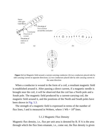
Figure 5.2 (a) Magnetic field around a current-carrying conductor; (b) two conductors placed side by
                side carrying current in opposite directions; (c) two conductors placed side by side carrying current in
                                                      the same direction


                  When a conductor is wound in the form of a coil, a resultant magnetic field
               is established around it. After passing a direct current, if a magnetic needle is
               brought near the coil, it will be observed that the coil has a North pole and a

               South pole. The magnetic field produced by a current-carrying coil, the
               magnetic field around it, and the positions of the North and South poles have

               been shown in Fig. 5.3.
                  The strength of a magnetic field is expressed in terms of the number of
                                                                                     8
               flux lines, f and is measured in Webers, where 1 Wb = 10  lines.


                                             5.1.2 Magnetic Flux Density

               Magnetic flux density, i.e., flux per unit area is denoted by B. If A is the area

               through which the flux lines emanate, i.e., come out, the flux density is given